Many readers will be familiar with the Rohloff Speedhub, a 14 speed bicycle hub gear, and if you don’t know about it then you can go look it up on Google. Understanding how the mechanism works and pulling one apart have been a couple of my long term goals. This article won’t attempt to communicate the former (that is for a separate article I think) but I am going to tell you about how I pulled my hub apart and put it back together again (that is quite important too). You may want to go brush up on your knowledge of epicyclic gears right about now too, because I’m not doing any intro to that topic, it’s all assumed knowledge. Wikipedia has a very good article on the topic.
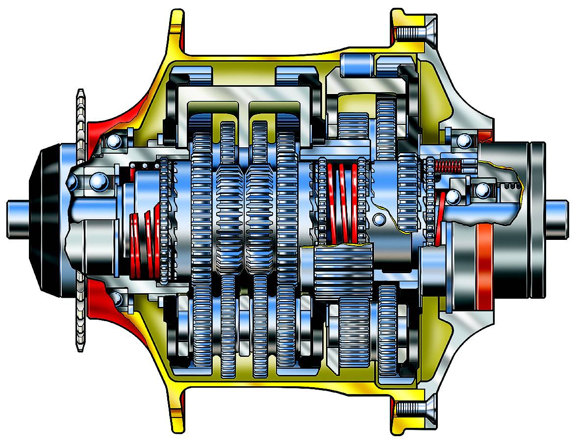
The story begins with this picture (click on it for a bigger version). I found it particularly useful in understanding how the mechanism works because of how it shows all four clutches. However, as I got a clearer idea of how the second stage worked (being the bit on the right hand side with the sun gear that has two clutches inside it) I noticed that there was a mistake in the diagram. The right most clutch (let’s number them #1 thru #4, so it is clutch #4) is drawn with the teeth facing in the wrong direction. I’ll try to explain what is going on: The first stage of the gear box drives the sun gear of the second stage, turning it clockwise when you look from the sprocket end of the axle. The output from the second stage is through the planet cage, which drives the hub via a set of nylon pins. Consider what happens when you turn the sun gear against the load resisting the motion of the hub (and hence the planet cage): the planet gears will try to turn the gear ring backwards. When the reduction gear is engaged, this backwards rotation is resisted by the teeth of clutch #4; such that when the gear ring tries to turn backwards, its clutch face locks with the teeth on clutch #4, and clutch #4 is held to the axle by its outer splined edge. And now you can see how the image is wrong, because the way clutch #4 is drawn, it would allow anti-clockwise rotation and prevent clockwise rotation. FYI, when the direct drive gear is engaged, the gear ring and sun gear are connected with clutch #3 and the whole stage 2 assembly rotates as one unit. In this situation, the gear ring overruns clutch #4, as the direction of the teeth permits the gear ring to rotate clockwise against the axle.
Whew. I bet that’s got rid of everyone who doesn’t have an engineering degree. So anyway, now that I was very sure of the mistake, I emailed Rohloff about it. I soon got a reply back; it was from a customer service guy, which probably explains a lot. He burbled away a bit about how the second stage works (all of which I already knew) and then basically asserted that there was no mistake on the diagram without addressing the point that I had tried to make. Now perhaps I didn’t explain what I had found clearly enough, but I suspect it was more that he himself didn’t understand the workings, after all he is (presumably) not an engineer. So the point here is that Rohloff denied the mistake, but I was certain that the diagram was wrong. BTW, I’m not completely sure that that diagram was in fact produced by Rohloff (I found it on Sheldon Brown’s site) but they didn’t just say it wasn’t their diagram, so…
[edit: According to John Harland the image does indeed originate with Rohloff; and I have since managed to find it on their website]
I decided that the only way to definitively prove that I was right was to pull a Rohloff hub apart and take some photos of clutch #4, illustrating that the teeth resist anti-clockwise rotation of the gear ring.
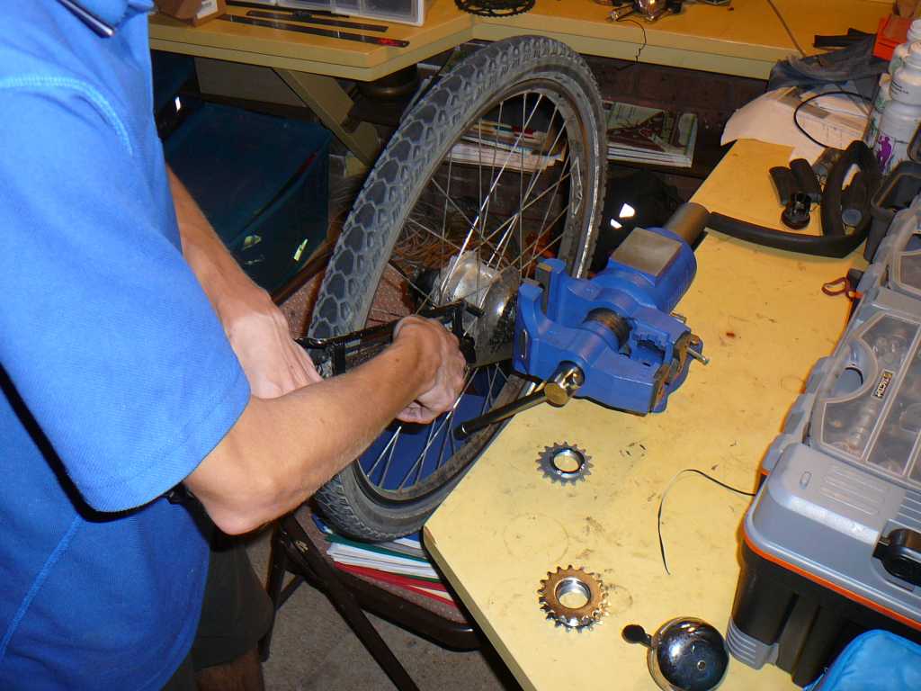
Removing a Rohloff sprocket is notoriously difficult.
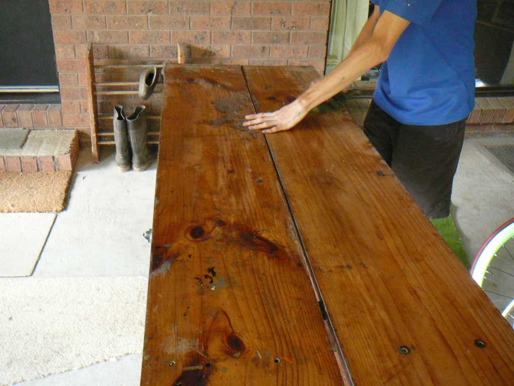
Clean your work surface with a damp or oily cloth.
Undoing the hub cap bolts. A star formation is best to avoid deforming the gasket mating surface.

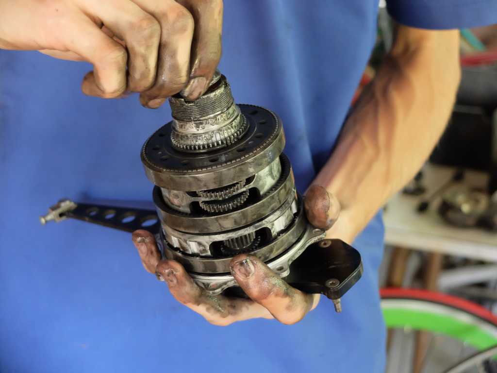
Internal assembly removed. Take care not to lose any of the nylon pins.
The nut that holds the internals together is quite tight; I used a vice to loosen it off.
Driver, with bearing cartridges visible inside it.
Clutch #1.
Using a small magnet to pull out the pin in the collar that retracts clutch #1. With this pin pulled out, the collar lifts off the top of the axle.
By keeping the two gear rings meshed with the planet gears, we avoid needing to align the timing marks during reassembly; a fiddly and time consuming task.
Clutch #3 sliding out of the hollow sun pinion. Note clutch #2 on the bench beneath the spring.
Lifting out the sun gear.
Again, keeping the planet gears meshed while removing the second stage of the gearbox.
This piece has clutch faces on both ends that engage the gear ring with either clutch #3 or #4, switching the second stage between direct drive or a reduction gear respectively.
The last couple of shims.
This collar connects the outer splines of clutch #4 to the hub axle.
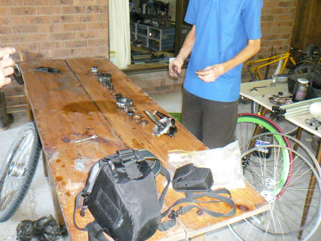
Disassembly complete. Parts are laid out in the order that they came off, for simple reassembly.
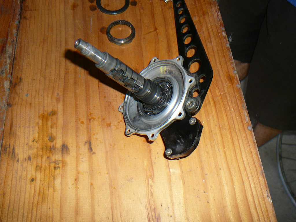
See, I was right.
I found it was easier to place the sun gears back into the first stage prior to sliding the whole assembly onto the axle.
Stage 1, complete with all 4 sun pinions inside, goes back onto the hub axle.
There were no bits left on the table, which was very satisfying.
A daub of grease really helps secure the nylon overload pins.
This little project ended up on the back burner for a while until one day when I went over to see John Harland, a friend of mine. He had an old hub (well actually just the internals of an old hub) which had apparently been playing up in certain gears, and he wanted to take it apart to inspect the pawls underneath the four sun gears in the first stage of the gearbox. As it happened, there didn’t seem to be much wear on the pawls or either of clutches #1 or #2 (we only disassembled the first stage of the gearbox), so the malfunction remained an enigma. Anyway, disassembling it was quite straightforward, following a technique that we had seen elsewhere on the internet, but reassembling it was quite tricky. The compound planet gears were difficult to reassemble: in order for them to mesh properly with the sun gears and the gear ring, they must each be placed with a timing mark correctly aligned. The timing mark is a tiny little dot on one of the teeth, and it takes good eyesight and good lighting for you to be able to see it properly. In the end, I had to head home with John still trying to reassemble his hub, being out of time. John did manage to put it back together though, after discovering via the internet that the timing teeth don’t mesh simultaneously, but are staggered by 1/3 of a tooth. Later still, I figured out a new technique to take off the planet cage without losing the timing alignment: simply keep the gear ring meshed with the planets. The two gear rings and planet cage (lets call it the first stage assembly) can be lifted off the axle, and if all the planets are meshed with the gear ring then they can’t rotate independently of one another and you don’t lose the timing.
I eventually decided to pull my own hub apart in December, when I was planning to do an oil change, in order to test my new disassembly technique and also to gather proof that I was right about the diagram. Combining the disassembly and oil change was a good choice because it is necessary to drain the oil before disassembling the hub; I then refilled it with fresh oil after reassembly. This avoided wasting oil (and the Genuine Rohloff stuff isn’t cheap either, so this really was well played). John Harland was kind enough to come over and take lots of photographs.

Now to how I pulled apart my hub. Before I started, I put the hub into gear 11. You could also use gear 4 if you wanted, the main thing is to put it in a gear where all of the pawls are retracted. I had also drained the oil the previous night.
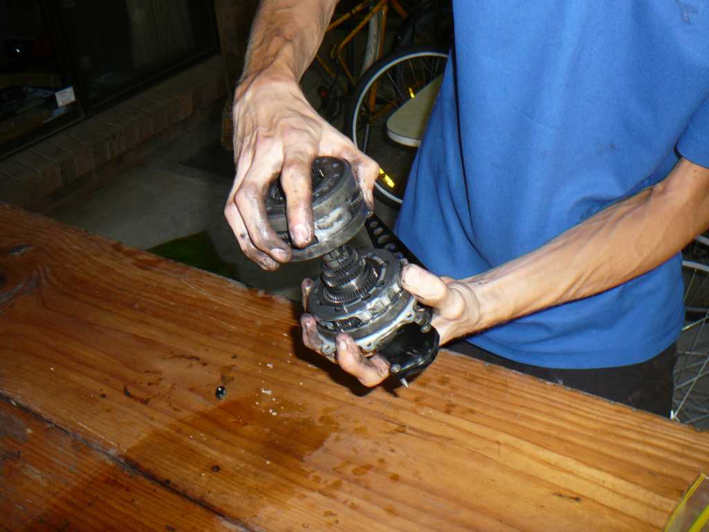
So, first I had to remove the sprocket, which is notoriously difficult because it is tightened by the chain when you pedal. I have found that using a vice to hold the sprocket removal tool helps, and I also used a length of metal tubing on the end of the chain whip to provide extra leverage. It really does take an enormous amount of force to make the thing budge. Perhaps I will go into detail of the other techniques I have tried in another article, but basically the longer your lever arm the easier it will be for you. At this stage I also set up a large table to work on, and cleaned it with a moist cloth to clear the surface of dust. Rohloff hubs aren’t cheap, so you really don’t want to get dirt inside them.


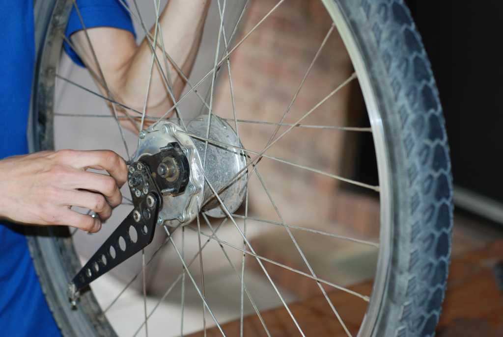
Next I unscrewed the hub cap bolts. It is best to undo them progressively and in a star formation in order to avoid placing an uneven stress on the surface that seals against the gasket. If the surface gets deformed, it will not seal properly. My hub has 8 bolts, so I loosened every third one, and I also undid them in 3 passes; but I think this is probably more important when tightening them up. Still it doesn’t hurt. Also, with the sprocket removed, the hub will dribble oil all over the place if you lie it with the sprocket side down (even after you have drained the oil out, some still remains in the hub), so don’t do this on your nice carpet. It would probably not be a very good idea to do it on your friend’s nice carpet either.

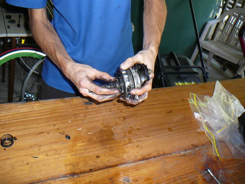
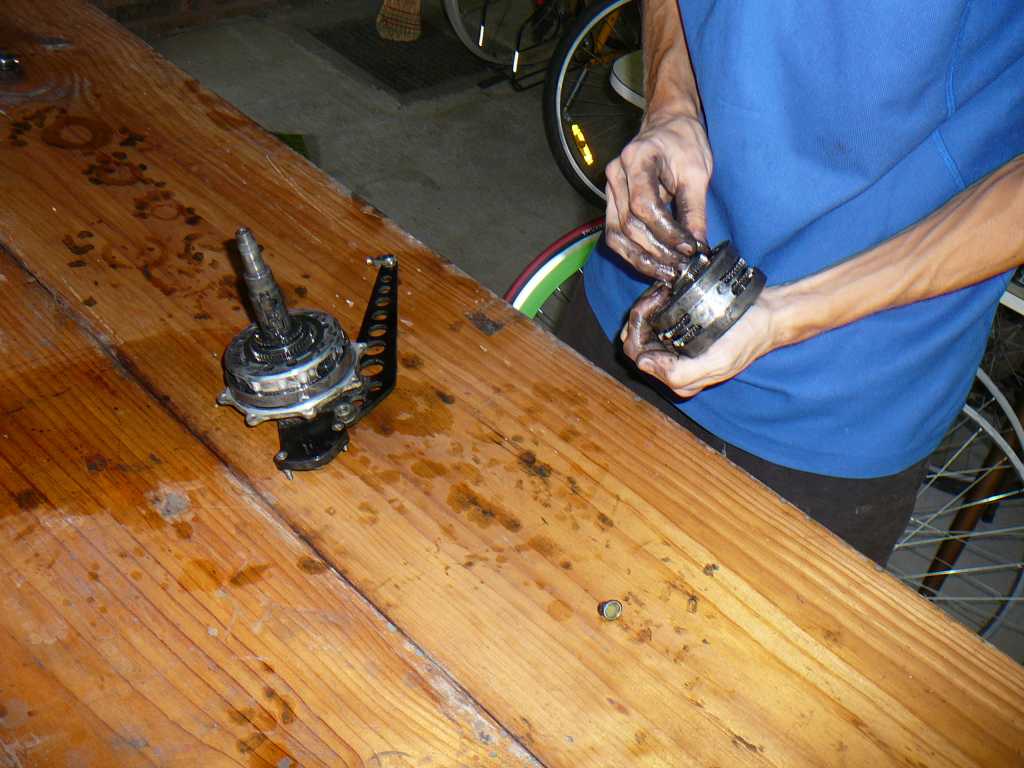
The next step is to gently pull the internals out from the hub shell. Apparently they can sometimes be hard to remove, because the manual suggests using a nylon mallet, but mine came out very easily by hand. Be careful of the paper gasket which in my case stuck to the hub shell. If you tear it you will have to replace it; I actually bought a roll of gasket paper from a bearing shop just in case, and if necessary I could have traced out the shape and cut out a new gasket. Fortunately I didn’t have to. Also watch out for the nylon pins in the internals, as they are easy to lose if you drop them (I put them in a ziplock bag). There are nine of them, and they actually function as an overload protection: If you exceeded the maximum input torque of the hub, the nylon pins would break before anything else (such as gear cogs). The nylon pins are cheaper to replace, and a lot easier, compared with replacing stripped out gears or clutches.

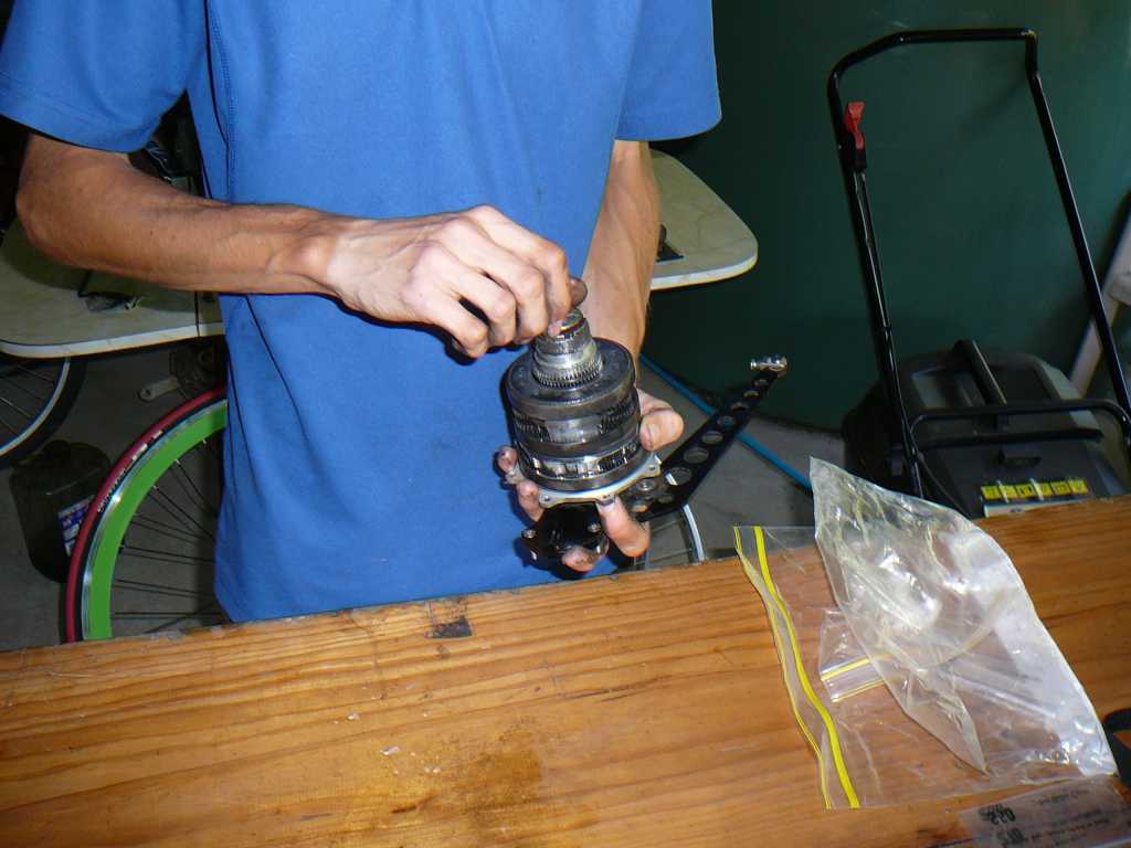
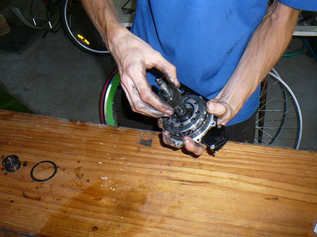
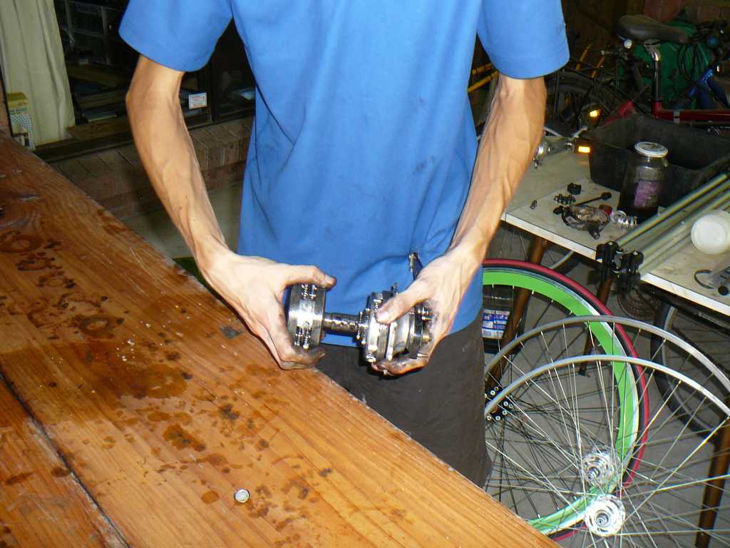
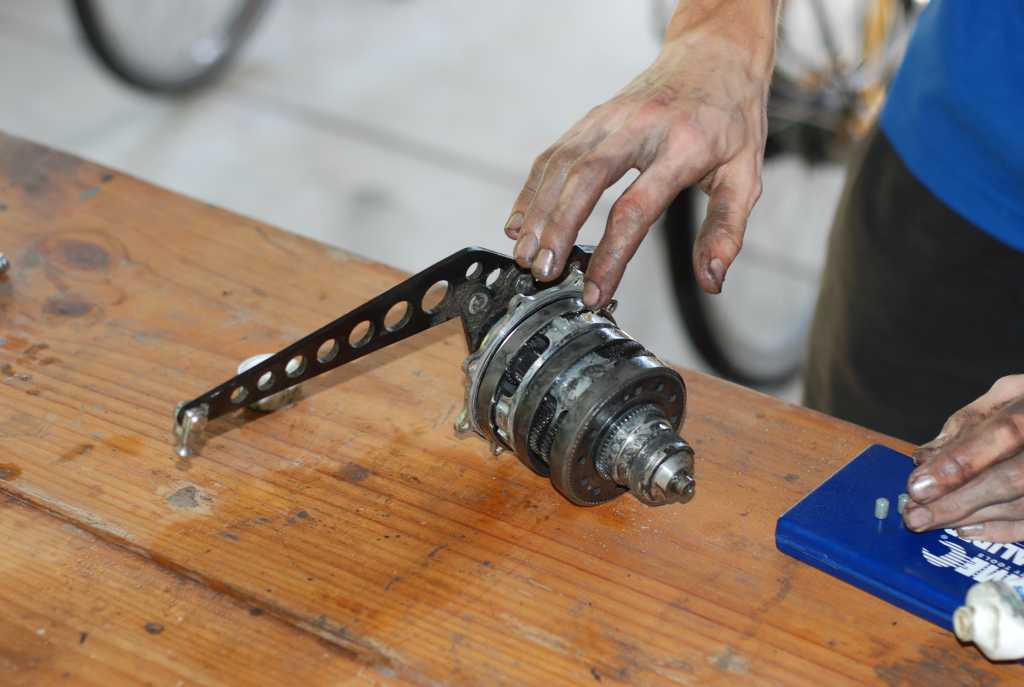
With the internals out of the hub, the only thing that holds them together is a nut that is screwed onto the axle next to the driver. It is quite tight, so to loosen it off I clamped the flats of the nut in the vice and then turned the axle using the torque arm to provide a bit of extra leverage.

The next thing to come off was the driver, but you need to be careful that clutch #1 doesn’t come up with it, if its splines stick within the grooves inside the driver. I then placed the driver upside down on the bench with the clutch spring inside it and clutch #1 on top of the spring, in order to keep track of how it went back together. There are a lot of bits in a Rohloff hub, and I knew that I would need plenty of space on the table to lay everything out.

Now there was just a collar that moves clutch #1, and that needed to come off before I could move the first stage assembly. It is held in place by a small steel pin that engages with a cam on the gear change shaft. It seems like the only way to pull out this pin is using a magnet. The pin is quite small too, so I was careful not to lose it; I placed it back into its hole in the collar and placed the whole thing on the bench.

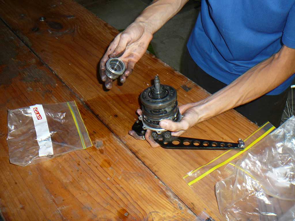
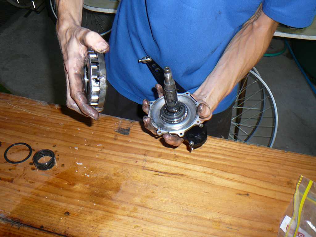
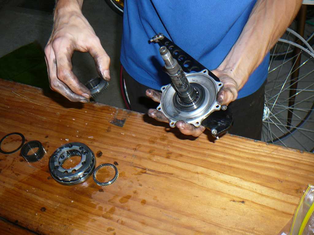
Having done that, I was able to lift off the first stage assembly. I wiggled it a little bit to make sure that the second (lower) gear ring was separated from the sun gear of the second stage. Two of the sun pinions in the first stage came off inside the assembly, but the other two stayed on the axle, which is not a problem. This is the part where it matters what gear you left the hub in, because if all of the pawls are retracted, the sun pinions will slide off the axle very easily. If some of the pawls are sticking up, then the neighboring sun pinion will catch on it when you try to slide the assembly off (or back on again).

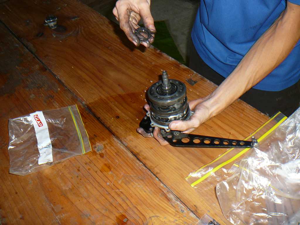
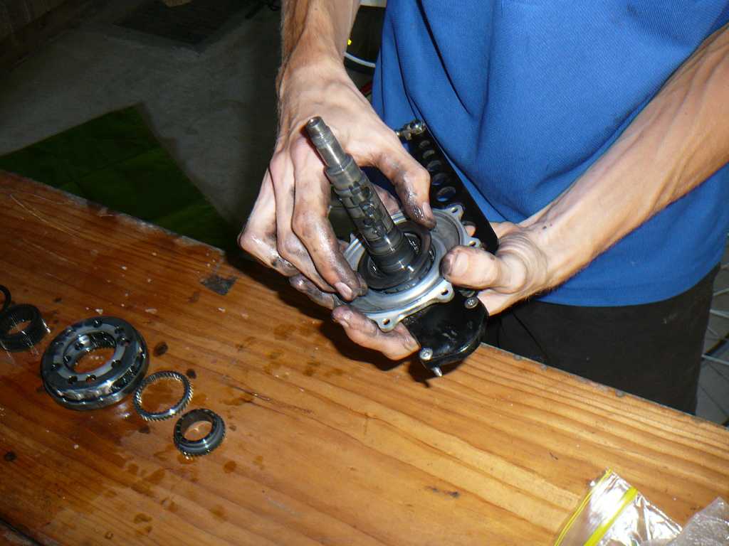
Next up was to remove the second stage. The large sun gear is hollow, and has two clutches inside it, #2 and #3, separated by a spring. An interesting point to note is that clutch #2 is not controlled by a cam on the shifting shaft as clutches #1 and #3 are. In the gears where clutch #2 is not engaged, such as gear 7, the clutch ring overruns the clutch face on the sun pinion, like a freewheel mechanism. If you have good ears you can detect the sound it makes while you are riding, particularly in gears 5, 7, 12 and 14. Anyway, I removed the clutches and spring, tipping it up to let clutch #3 slide out, remembering the order they came out in.

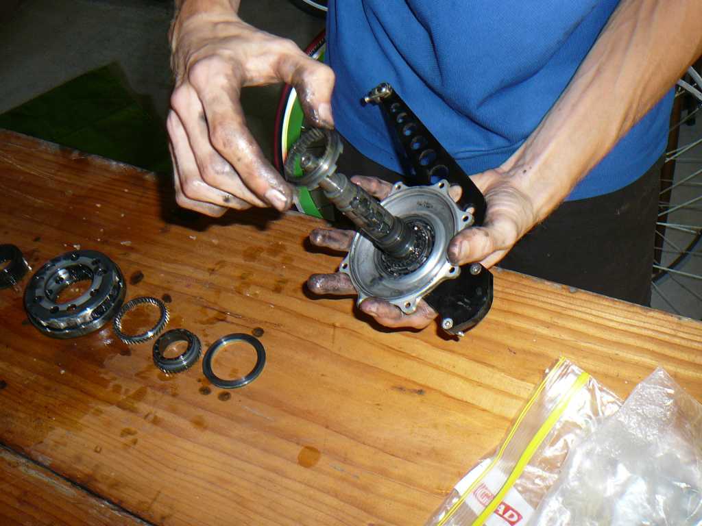
After I lifted off the second stage assembly (same as with the first stage, I kept the gear ring meshed with the planet gears so that I didn’t have to fiddle around with the timing alignment) there were just a few bits still to go. There is a collar with clutch faces on either end which has splines around the outside that fit into the inside of the gear ring’s disk. There is also what seems to be an aluminium ring, like a spacer that sits between the gear ring and the freewheel ring collar.
The black part that you see in all of the gear ring disks is not metal; it is either carbon fiber or some other plastic or resin based material. This is partly why you can’t just use any old oil in these hubs, because short chain hydrocarbon molecules can permeate and damage the resin/plastic/carbon fiber parts (maintaining viscosity is the other issue). Ordinary lubricating oil, which is refined from the stuff they get out of the ground, consists of a mixture of different molecule sizes with a spread like a bell curve, ranging from short to long hydrocarbon molecules. Whale oil was one alternative used by early automatic transmissions in cars; it is produced in the whale by a biochemical process that makes lots of the same molecule, so instead of a range of molecule lengths, it is all the same length. This meant that the oil did not change in viscosity (because there were no small molecules that evaporate easier), which is an important property for the speedhub. Synthetic oil is also all the same molecule, but it is made by an industrial chemical process, and thus no whales are harmed in the manufacture of modern automatic transmission fluid and Rohloff oil. But I digress.

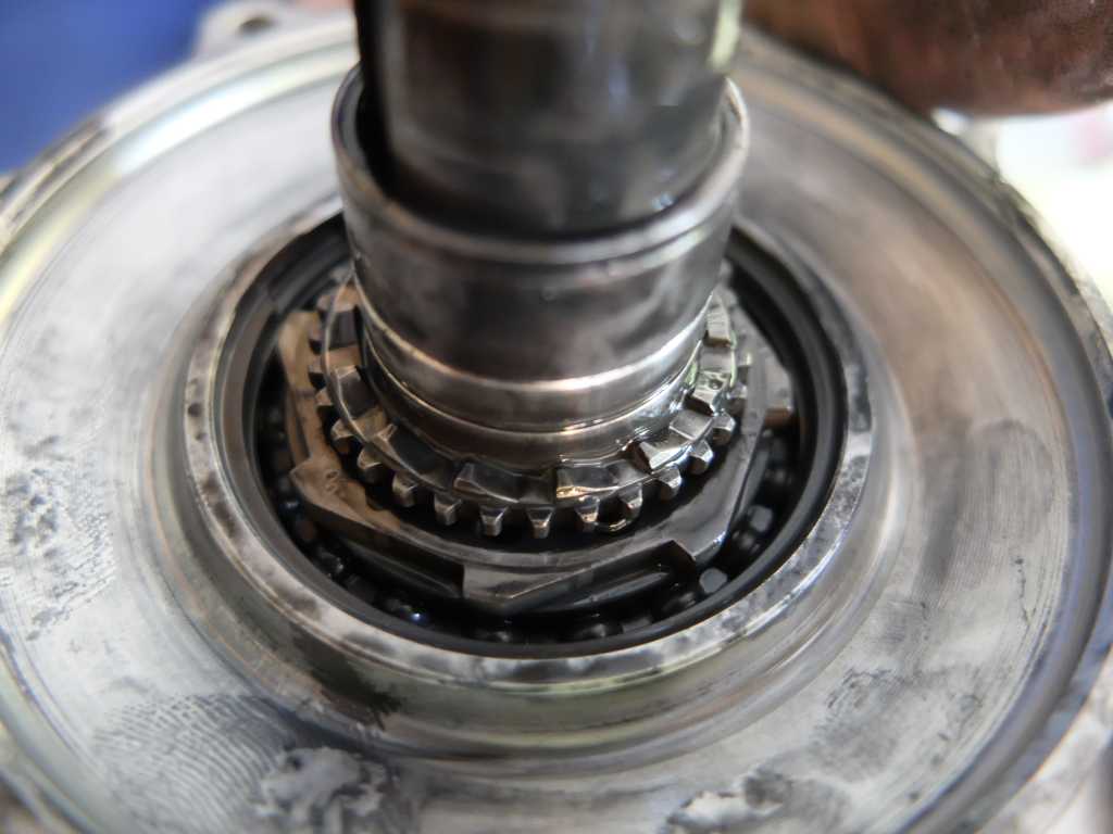
I removed these last few parts (careful to keep track of the order they came off in), and soon exposed clutch #4, to see that I was right ha ha ha.

Now we come to how I reassembled it. Keeping the planet gears meshed with the gear rings was a very good move because it was much easier to put them back together. It was a little fiddly getting the splines on the gear ring disk to line up with the part that they slid onto, but nowhere near as time consuming as it was to align the timing marks on John’s hub.

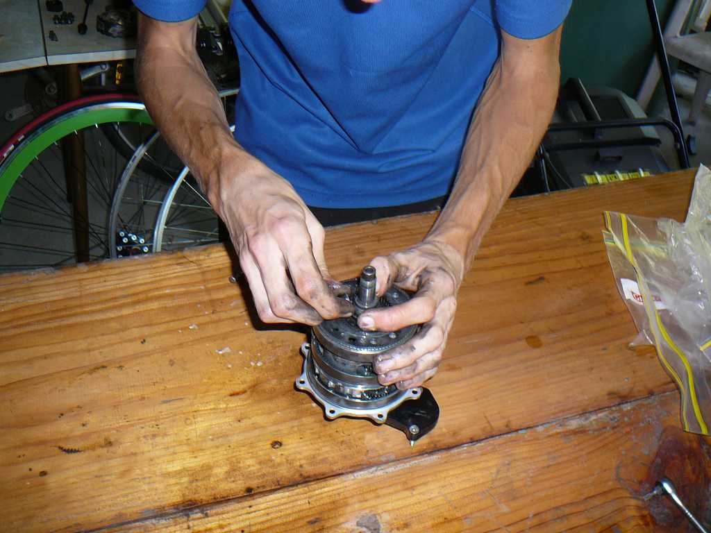
When we got to putting the first stage assembly back on it got a bit interesting: it was quite difficult to insert the sun gears on the axle, so what I ended up doing was I placed the sun gears into the first stage assembly on the bench (turning the gear ring a bit helped coax them into meshing) and then I slid the whole thing, sun gears and all, onto the axle. It was very helpful for this that all of the pawls were retracted, which meant that the sun gears slid onto the axle easily with nothing for them to catch on.

It was then straightforward to replace clutch #1 and the driver, tighten up the retaining nut and we were basically done. I found that a small amount of grease was very helpful to hold the nylon shear pins in place while we slid the internals back into the hub shell; after a few attempts we also found that one of the slots was perfectly lined up with one of the hub cap bolts, so we could use that as a guide. After tightening the hub cap bolts, tightening the sprocket and refilling the hub with oil, I was soon able to take the hub out for a quick test run, partly to satisfy my Dad. John and I invited him outside where we were working just after we had completed disassembly; Dad’s expression of horror was quite entertaining.
The following day I took it on a longer ride in hilly terrain where I tested out pretty much all of the gears, and it worked perfectly. In theory, this technique could also be used to replace a chewed out clutch or pawls with minimal fiddling around (and no exotic tools either, other than the sprocket tool, but they’re easy enough to acquire), but in practice it is very rare for such replacement to be called for. These hubs are very reliable for a very long time.
[Update: I did eventually get around to sending Rohloff pictures to indicate what I meant by saying the diagram had a mistake, and they did concede that I was right]
After a bit of a search I found again the link for indexing the pinions: .
Thank you from Canada for your quality post. It’s hard to find well done “take it apart, put it back together again” articles. I’m a machinist by trade, and I’ve been thinking about incorporating a SpeedHub into a shaft-driven chopper with a CNC real wheel. Therefore, I was glad to see that the sprocket is mechanically simple to replace. It would appear that moving to a pinion gear will be trivial. I was also glad to see that the entire internal assembly could be removed from the outer shell in one go — I had nightmarish visions of opening the unit only to have 200+ loose pieces fall out on the table. Given my intentions, picture #4 of 22 was my favourite — I’ve been dying to see the inside of the outer shell to see how complex it would be to machine a new one. I had been afraid that the ring gears might be part of the shell or whatnot. It would appear that I only need to deal with two or three radii (one of which is the sprocket-side bearing surface) and a handful of lateral grooves for the nylon overload pins. Do you concur? Are the black strips inside the shell just the paper gasket(s) that you spoke of, or are those circumferential grooves that I need to turn?
Thanks for any tips, advice or feedback that you might provide.
I’m curious to know, would that be a shaft driving a Rohloff hub, or a Rohloff hub driving a shaft which drives the rear wheel?
Rohloff hubs have been used as intermediary drives (ie the hub drives the rear wheel via a second chain) previously, but I’ve only heard of it being chain driven. It’s not all that complicated to set up; the bolts for the Rohloff disk brake rotor are the same pattern as for a 4 bolt MTB granny chainring, so that approach doesn’t require machining.
On the sprocket side of the hub there’s also a recess for a circlip next to the hub bearing surface.
Also, in answer to your question the black strips in the photo aren’t gasket paper, but oil and other gunk (metal particles etc). The main gasket which seals the hub cap is actually visible around the hub cap bolt holes. It stayed stuck to the hub shell so I didn’t remove it, since that would risk tearing the paper which would be inconvenient. Not disastrous though; I’d bought some gasket paper beforehand just in case.
Your project sounds very interesting though.
I’ve seen one or two of those intermediary drive arrangements, but that’s not what I had in mind.
Instead of a conventional diamond frame, I’m planning on building a triangular frame, whereby two top tubes run clear from the headset to the rear dropouts, and two stays run from the bottom bracket to the rear dropouts. I’ll have a single down tube and no seat tube. Their will be no head tube per se, but a machined lug containing the headset and orifices to receive the down tube and top tubes. I’ll do a raked triple clamp to keep the trail manageable. All five tubes will be arrow straight. I plan on machined lugs for the rear dropouts and for the bottom bracket. The saddle will simply bridge the two top tubes immediately in front of the rear wheel. All lugs and tubes are to be aluminium. I intend on brazing all of the tubes into the lugs. Here’s an image of something with similar geometry:
http://www.roadrecumbent.com/pink_op_800x501.jpg
The kicker for the drive train is that I plan on building a ring gear inside of the (unusually large) bottom bracket, and stealthing the drive shaft INSIDE of the drive-side stay. The shaft will have pinions on either end, and the SpeedHub will be in its usual location in the rear wheel, though in a CNC rim. Since none of the gears will mesh at nice, neat on-centre 90-degree angles, it’ll all be helical teeth. My drawings have means to access the shaft via ports in the lugs, and to independently set the thrust on each pinion (which is NOT going to be fun, but which will hopefully be a one-time gig).
Sorry for the long-winded explanation. It’s the first time I’ve tried to explain it in words without just showing someone my book. =) I’ve got an entire book of pencil drawings I’ve done of various details, but nothing digital so far. The design is most certainly over the top, and it might be a while before I see any progress, as the missus and I have three little ones, but that’s my dream.
Thanks again for your blog and your response!
-jj
On the one hand, I’m saddened. I just thought my Rohloff worked magically. On the other hand, thanks for a great tear down article.
Could You provide me with a bit of information regarding the 9 nylon pins-I would like to know the dimensions. Thak You
Why yes, I’ve just measured with calipers, and they seem to be 8.8 mm long by 6.0 mm diameter cylindrical nylon pins. I think you could round up to 9 mm by 6 mm if that was what a shop had available.
The pins provided in Rohloff’s hubs also have a slight bevel on one end which would make it easier to mount the internal assembly in the hub shell.
Strangely I couldn’t find any sign of the nylon pins being sold as a spare part, not even from SJS Cycles who do stock gaskets and many other Rohloff parts.
This was an excellent read. Thank You for taking the time and contributing in this way.
You’re welcome
Thanks for great info.
Is it hard to remove the axle from the hub cap?
Is the axle pressed in bearing?
Correct, the axle and hub cap are pressed together, and seem to be difficult to separate by hand.
In terms of tools, something similar to a flywheel puller should work, but I haven’t seen any commercially available tools that are the right size and shape. You need something that will support the inside of the hub cap while pressing down on the axle (probably a screw thread to press out the axle).
Also consider how to reassemble (or install a new hub cap). Banging them back together with a mallet would probably work. A press would be nice though; perhaps it would be possible to use the axle plate mounting holes to attach a press (similar to the way the bearing seal press attaches).
So if you’re keen, you could fabricate the required tools and do the work yourself. Alternatively a good bike shop that deals with Rohloff stuff should be able to do it for you (although I think most of them will send the wheel back to Germany for this kind of thing).
I’m interested to know why you find yourself wanting to remove the hub cap? Conversion to disc brakes?
Hello Matthew,
I am having a real tough time attaching stage 1 onto the axle. I have managed to fit in all 4 sun pinions but the moment the ensemble is moved onto the axel the pinions move and cannot get it to fit into it’s place. The sun pinion 1 is obstructed by a pawl I have to manually push in so that it gos in right way but then all other sun pinions fall out of place in the carrier. It seems like such a dumbfounded “technical” solution, the pinions being loose like that; I mean, compared to this, the Alfine 11 is way more sturdy.
Would you perhaps have any tips on how to tackle installing the whole stage-1 carrier onto the axle? I am burned out from fiddling with this thing for the past couple of days, hours on end.
Thank you kindly.
Best regards,
Alex
Firstly I recommend setting it to either gear 4 or 11, so that all of the pawls are retracted and won’t obstruct the sun gears when you put the first stage back on. Note that the pawls will fall out when you change gears but they’re not hard to put back on; the ends of the pawl spring should sit in the small groove on the back of the pawl.
Another way of reassembling the first stage is to put the first two sun gears on the axle, then fit the first stage assembly (with remaining two sun gears fitted) over the top. Turn the ring gears and planet cage a bit to align the splines (but be careful they don’t come apart or you’ll need to re-align the timing marks). Once they align they should drop together very easily. Placing sun 3 and sun 4 first helps by keeping the clutch ring for clutch 2 inside sun 5 (otherwise it comes out and can get misaligned).
I’ve also found that holding it so the axle is horizontal helps, because that way the sun gears don’t tend to fall out of position due to gravity. Provided it’s in gear 4 or 11 (as above).
I hope this is helpful
God bless you, dear Matthew!
You really saved my bacon, man! Using your tips I finally managed to fit it all onto the axle. Beforhand, I was attempting to fit them in in 14th gear, it was impossible, as you know. It went surprisingly smooth considering what I had been through.
At first I missed th last shim right next to the driver and the ensemble had a very draggy spin but checked to see if any pieces were left behind, installed the missing shim and now everything spins very smooth indeed.
This is a 2003 hub that had never been serviced and the cog was well elded shut to the driver. With the help of a machinist friend, I managed to fit in a sleeve over the driver that will take Nexus/Alfine cogs; it is a sight, as you can imagine.
Your help was indeed invaluable, brother. Wish I could shake your hand and buy you a cold one, sir. Most sincere thankyous for taking the time to post these stripoffs and helping the occasional deer in the headlights of the interwebs. Literally could not have done it without you!
Wish you and yours all the best.
God bless!
Matt, I just wanted to add that by using your method of attaching stage-1 with the ring gears and the shims onto the carrier, the sun gear 2 is pushed up and dislodges the upper sun gear 2 and the upper sun gear 1 so that the moment I try to install the driver, it would not fit in onto the upper gear ring 1. Looking into the carrier with a flashlight, the lower sun gear 2 doesn’t sit fit onto the lower sun gear 1. I can’t find a good way to make it go down fit.
Thank you kindly for your help,
Alex.
Hello Matthew
Can you explain what is the purpose of pawl springs on the shifting shaft? Are they for rising the pawls (engaging with sun) or for lowering the pawls (disengaging with sun)? I am asking this question because part of this spring fell out during oil change, so something should be wrong, but hub seems to be working fine (but maybe not for long as parts of this spring will cause wear to gears).
The pawl springs act to raise the pawl to engage with the sun.
Correct me if I’m wrong, but it sounds like when doing the oil change and draining the old oil plus rinse fluid, you’ve noticed one (or more) metal fragments that came out through the oil drain hole. How sure are you that it’s one of the pawl springs? Alternatively, it may have broken off the shifting shaft, the freewheel springs, possibly broken gear teeth, or maybe (although I think this would be very unlikely) from a clutch ring. I would want to clean out any other possible fragments to prevent further damage, but you may prefer to send it off to Rohloff for that depending on how confident you are to pull it apart.
The pawl springs have two legs on them, so the hub may continue to function if only one of the spring legs has broken. Otherwise it would malfunction in certain gears, giving either no drive (pawl 1 or 2 numbered from the sprocket side), or the wrong gear (pawl 3 or 4).
I’m very interested to hear what Rohloff think about it.
Yes you are correct. I’m 90% sure that the piece wich came out with oil is part of pawl spring, because it is a piece of wire about 4mm long and 0,5mm in diameter with a similar bend as pawl spring has (as far as I can tell looking at exploded view). It is a second hand hub and I don’t know its history maybe someone messed with it already. I’m also worried that cost of repair at Rohloffs will be very high and that’s why I’m wondering if I can fix it myself. Disassembly doesn’t seem to be difficult at least to the point where I could see the pawls and check the condition of the rest of internals. A spring also seems to be one of the easiest parts to manufacture from all the hubs parts.
Ok.
One trick that someone else showed me is that you can lift off all the gear sets together, lifting from the third ring gear (after removing the driver and first clutch etc, and selecting gear 11). All of the sun gears are held in the assembly, and clutch rings 3 and 4 remain on the axle (and the rubber silencing o ring). This would give you easy access to the pawls for inspection.
The pawl springs are quite fiddly to remove, but I’ve done it using a fine screwdriver and tweezers.
Sourcing a replacement spring is another challenge. Ideally you would be able to buy it from Rohloff, and I suppose you could always try. Send them a picture of the broken spring, and explain that the hub is (presumably) long past the warranty anyway and you prefer to do the work yourself. If Rohloff say no, the alternative might be to fabricate the replacement from the right gauge of spring steel wire.
Thanks for all the tips. I’m starting to think that I might be wrong and the wire is not a part of pawl spring. Yesterday I tried very hard to make the hub skip and it didn’t, and that just couldn’t be right if the pawl spring would be broken. I did measurements properly and gage of the wire is more like 0,1-0,2mm. It’s exactly the same as single strand of shifing cable (some old cable I had lying around). My theory now is that someone mounted the shifting cable improperly (internal mech) and it got frayed and broken than someone made it properly but didn’t find that piece. Moreover I contacted Cycle Monkey and looking at the photo they stated that it doesn’t look like a part of the hub. So for now I guess I will be riding the hub and wishing for the best, but think that someday in the future my curiosity will force me to take a look inside;) Thanks again for your time:)
Hello. You’ve done a great job describing the hub removal/assembly, will be very helpful to people. In my case the problem is with oil leakage inside the hollow axle. The logical cause is damage to the gasket marked #45 in the diagram.
To look into it I have to disconnect the axle. Can you tell me how to do it, is it difficult?
Correct, oil inside the hollow axle must have seeped past gasket #45. However, I think that gasket will normally seep a small amount of oil; my hub does and I know that the #45 gasket isn’t damaged.
If you wish to check anyway, fortunately the shifting & indexing mechanism is actually quite simple, and not too difficult to work on. Compared to say, Shimano 7/8/11 speed hubs (with their spring tensioned gear cables) those hubs’ control mechanisms are much more fiddly than the Rohloff.
I’ve been meaning to write another post covering the Rohloff indexing mechanism for several months, so I’ll have to get on with it.
Thanks so much for your efforts in explaining the Rohloff Hub, and awesome catch in seeing that the Clutching Teeth were inverted in the graphic. When I first saw this Hub I thought I’d never figure it out, but with the efforts of people like you I can now calculate each gear reduction or overdrive ratio. Thanks for taking the time to photograph your work.
Best wishes Matthew, God bless!