
Background
Readers who are familiar with bicycle touring will probably know about the venerable Schmidt SON (Schmidt Original Nabendynamo), being one of the more highly regarded hub dynamos. I will leave it to others to weigh up the relative merits of different hub dynamo brands; this particular hub has certainly served me well over the last few years, and I would be reluctant to part with it, mainly due to the fact that it’s relatively simple to pull apart for overhaul.
I actually didn’t acquire my SON28 new (nor even second hand). It was owned first by my father, from circa 2008 until early 2011, and then he passed it on to my mother who owned it from 2011 until early 2017, when I acquired it.
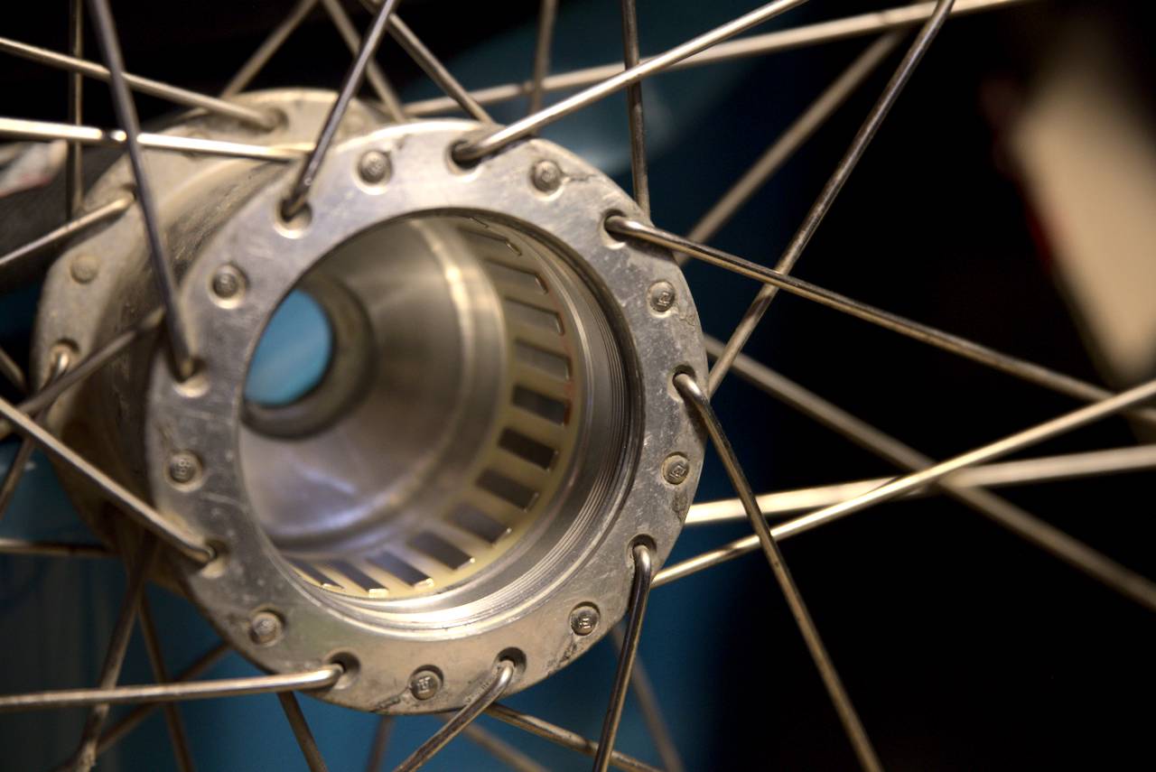
When you look at historic Schmidt hubs, you may observe that models from before around 2012 or so were made as a cylindrical hub, a variant that’s now discontinued as far as I can tell. However, when you look closely at that variant, you can see a tantalising spline pattern next to the terminals, and a circular line near the spoke holes, which suggests that the hub internals may be removed (with the right sort of tool). The type which is currently made is kind of spherical; the hub shell being made in two hemispheres which are pressed closed around the armature and axle assembly. Accessing the internals (eg to replace bearings) of one of these would require first unlacing the wheel in order to separate the two hub shell halves, which is possible I guess, but nowhere near as convenient as simply unscrewing the internals and not having to rebuild the wheel afterwards.
So, in 2017 when I decided to build myself a new front wheel with a Schmidt hub, I negotiated a deal with Mum which meant that I got the easy(ish) to service model in exchange for rebuilding her front wheel with a brand new Schmidt hub (the sort of spherical type).
Now of course, if one reads the marketing brochure from Schmidt, you may think that the bearings in SON hubs will last forever. Well, Schmidt actually say the “lifetime of the bike”, and I don’t think they ever anticipated the kind of service life that my hub has had. I know that I have used it for about 45,000 km of commuting and touring; and assuming my parents did about 5,000 km per year I would estimate that it has covered somewhere around 100,000 km all up.
With that in mind, it should come as no surprise that early this year (just after returning from a 3 week long camping tour) I noticed that there was a bit of play in the SON28 hub. It was not hugely severe, if it were an ordinary front hub (assuming cartridge bearings, as one would simply readjust a cup & cone type hub) you might not be all that concerned about the amount of play that there was: the movement at the tire was a few millimetres side to side. However, if you care to study a cross section diagram of the SON28, you will notice that the internal clearance between the armature and the magnets arranged on the inside of the hub shell is very tight; less than 1 millimetre. Such fine tolerance is (I believe) important to make the generator as efficient as possible, but it also means that even a small amount of misalignment between the axle and hub shell (due to play in worn out bearings, for instance) could allow the magnets to scrape on the armature.
Now, replacing the worn out bearings may be somewhat challenging, but replacing broken magnets (as I understand, rare earth magnets are quite brittle) or repairing damage to the armature would be another level entirely. For this reason I decided to prioritise replacing the bearings, and to avoid using the touring bike until it was done. I have other bicycles, so this was not so onerous; the most significant impact was that I wouldn’t really be able to do camping tours. Lucky thing none were planned for the next few weeks.
related literature
Fortunately for me, I’d already been considering the problem of how to open up my SON28 for some time. Even still, my research on this topic had turned up very little. I only found a single blog post by a guy who had successfully opened up his SON28, which I noted was the same model as mine:
In his case, the fault was not actually the bearings but rather rust on the inside of the hub; and hence he didn’t go so far as demonstrating how to remove the actual bearings. At any rate, removing the internals is without doubt the first step to get at the bearings, and so this post was very useful when I was considering ideas on how to make a tool to fit on the hub cap splines.
The comments on the other hand gave cause for concern, as it left me totally unclear on which way I would have to turn the hub cap in order to remove the internals. One comment said (paraphrasing) “hey, is the hub cap left hand threaded or right hand threaded”, to which the author replied “standard left-hand threads here”. A subsequent commenter asked “to disassemble, do I turn counter-clockwise?”, but there were no further comments from the post’s author to resolve the confusion. What did he mean that the threads are “standard”? The hub cap is a hell of a lot bigger than an M10 metric thread, and doesn’t match any fastener that I know of that might be considered standard. By standard, did he mean in a round-about kind of way that you turn it in the standard direction to undo a right hand thread? Why did he say it’s a left hand thread then? So many questions, but sadly it seems we will never know the answers.
By looking at one of the photos with my face about 2 inches from the computer screen, I sort of got the impression that it was a right hand thread. I also discovered information on Schmidt’s website that said the older SON28 Klassic hubs must be mounted with the terminals on the right side, implying that mechanical precession was taken into consideration. Mounting the hub the wrong way, precession would tend to loosen and even completely unscrew the hub cap; but mounted correctly, precession tends to tighten the hub cap. This effect is also relevant for pedals and bottom brackets. I did some thinking about how precession would work, and came to the conclusion that a right hand thread would be tightened by precession, apparently contradicting the comment I had read.
initial steps
Early in 2020, I had begun going to a maker space with John on Monday evenings, where I’d been learning about 3D printing. Even back then I was considering utilising it to fabricate a tool to fit over the spline pattern on the SON28 (although back then it was more out of curiosity to see if I could do it). The fact that I had access to a 3D printer at the maker space, and I didn’t have access to a milling machine (or anything similar) with which to fabricate a part out of metal, made 3D printing a logical choice. I had also taught myself enough skills with CAD software that I could design basic shapes. Armed with a set of vernier calipers, I began taking measurements of the spline pattern on the hub cap.
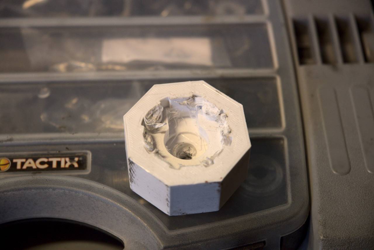
My plan was to produce a tool that reproduced the spline pattern (as best as I could with my limited CAD skills) and would also accommodate that end of the axle, and also the two electrical terminal blades. The initial version of the tool I decided to 3D print the spline pattern that fit into the hub cap. Although I had some doubt as to whether the plastic would be strong enough to do the job, I figured that if it wasn’t, I could easily reinforce the design a bit more by adding tougher material (probably steel bolts) to the splines. If the plastic splines broke, I also knew they would not cause any damage to the aluminium hub cap, the plastic being the softer material. I settled on making the outside of the tool octagonal, in order to be able to easily clamp it in the vice, and with a hole through which I would feed a QR skewer to hold the tool onto the hub.

After 2 attempts at 3D printing it (the first shot I found I’d got one of the measurements wrong, and it was too small by about a millimetre) I had the tool ready. I took it home, attached it to the hub (with some use of a hammer, one of the other dimensions was a bit tight which I later corrected). I set up the QR skewer and clamped the whole assembly in the vice, and after double checking which way to turn it (I was assuming a right hand thread, as that seemed the most logical), I held the wheel around the tire and began turning.
I must admit, even though the splines were plastic, they did withstand a surprising amount of force; I really put my weight into it. At first I thought the hub was finally unscrewing, but then I heard the tell tale crackling sound of breaking plastic, and sure enough, the plastic splines had sheared off.
version 2.0
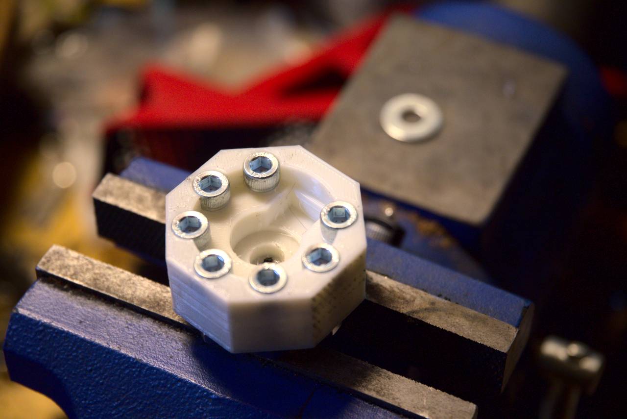
The next Agile sprint, if you like, lol. I looked at how the first version of the tool had broken, and I concluded that the only failure was that the plastic splines had sheared. The logical solution was for the splines to be a material with a higher shear strength. I had found by experiment that steel bolts with a 5 mm Allen key head (M6 thread) were just the right diameter, so I decided to add holes in the CAD file where the splines had been and to fit bolts into these holes.
This carried a somewhat ominous risk, because I wasn’t entirely certain that I was turning in the right direction to undo it. The plastic splines would definitely break before any damage to the aluminium hub; the same would not apply for the steel bolts.
From our local hardware store, I acquired suitable M6 Allen key bolts, as well as hex nuts and washers with which I planned to secure the bolts into the plastic body. However, after printing the plastic part, I found that the holes were slightly too small for the bolts to slide through. After tapping a thread into all 7 holes, I decided that threaded holes would probably be preferable, so I reduced the hole diameter and re-printed.
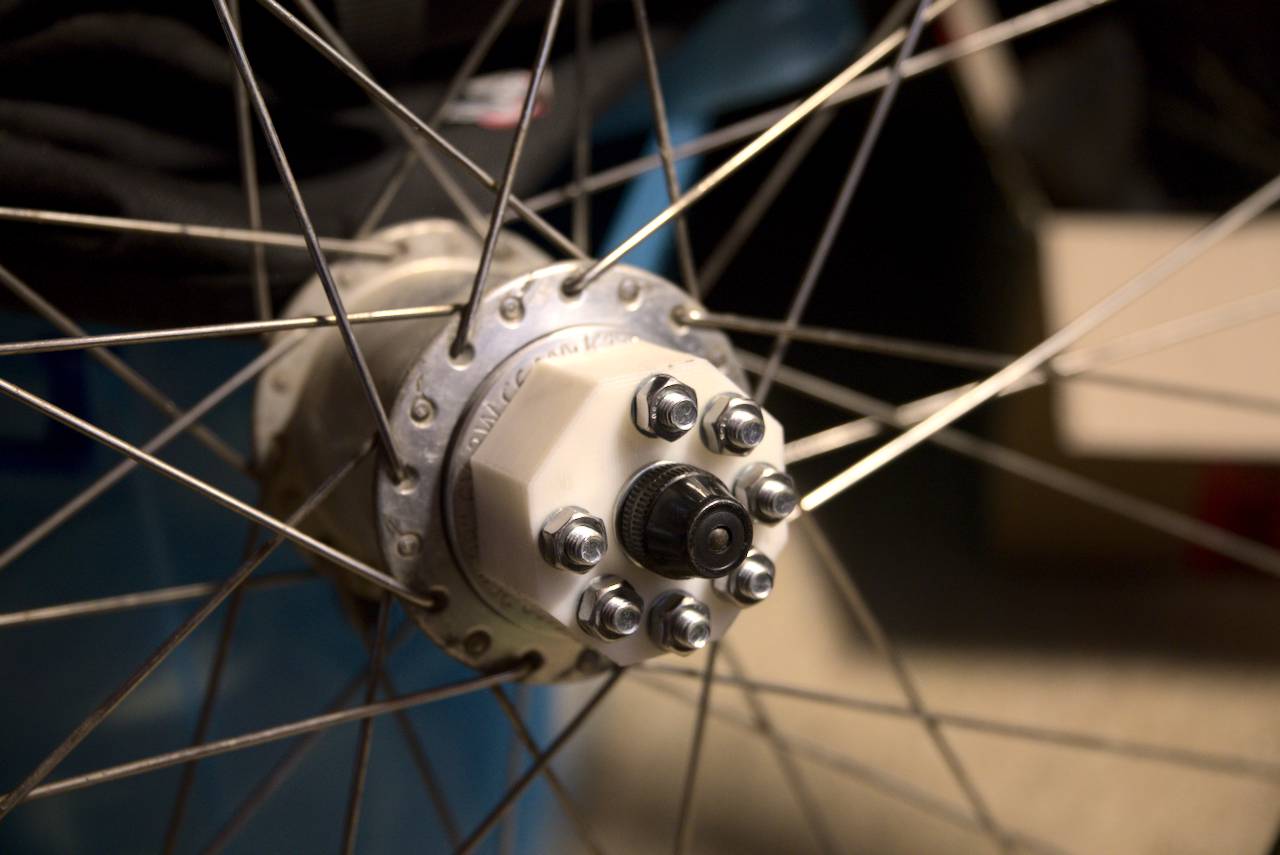
This version fit perfectly. It was a few days later that I had decided to make another attempt at opening the hub, as I had invited John over for a bike work day. After setting it up in the vice, once again I really had to put my weight into it, even though I was turning it from the tire, giving a tremendous amount of leverage. This time however instead of the crackle of splintering plastic, there was a sudden *clunk* and it started turning much easier. I stopped right away of course, but when I checked around the hub cap I could see immediately that it had begun to unscrew.
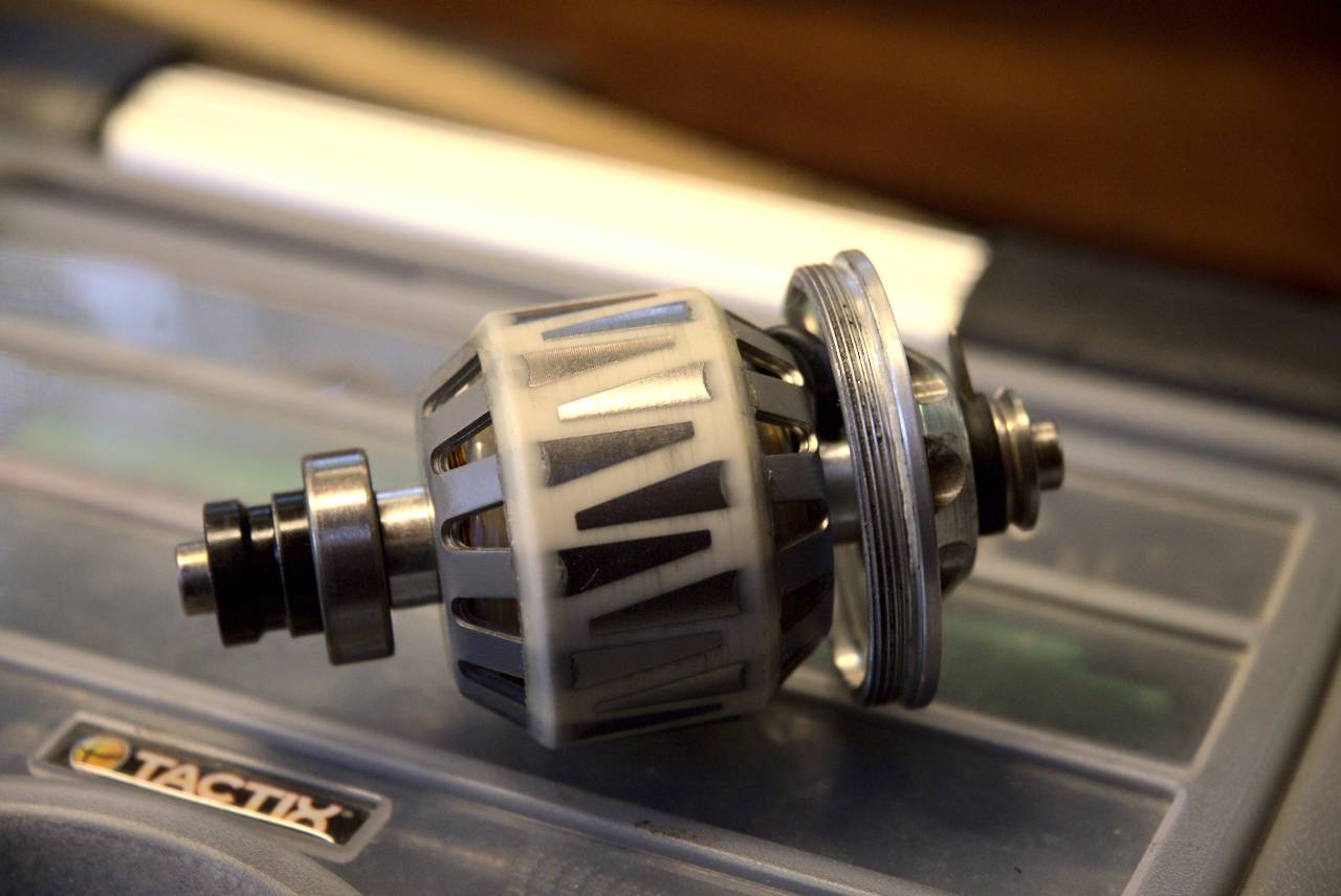
After I had undone the hub cap all the way the internals were still stuck in the hub body, which I presumed was due to the left hand side bearing not being quite out of it’s slot. A firm tap with a hammer was all that it took.
Having removed the internals meant that I could now begin to plan how I could then remove the bearings; the next phase of this project. Stay tuned for the outcome of that in an upcoming article.
Update: you can find the STL file for the plastic tool body here.
Update: The hub cap is a right hand thread, as you would expect to ensure that precession tightens the hub cap.
Wow! Amazing. I’m looking forward to the bearing replacement!
Nice work Matt. Looking forward to your next installment. I have the same version as your mum but I’m not sure how serviceable they are. It’s still relatively low mileage so not worried about it yet.
Hi Matt
Amazing work! I just love when creative people service parts that are “not user-serviceable”.
Would you consider publishing the 3D printfile for your SvS-1.2 (Signorini vintageSON Splinetool)?
Thanks in advance
Mark, Edinburgh
Hey Matt,
Stumbled on to your blog trying to address a problem of my own with a Panasonic dynamo hub and hoping you could give me your two cents. The problem occurred when I was seeking to adjust the hub (turns out it didn’t, just the dynamo resistance was a bit more than expected) and ended up damaging it. Specifically, I severed the wire coming out of the hub right at the bearing. I’m fairly handy with solder so I think I can repair it, but not sure if I can pull any of the wire out of the hub to have a little bit more to work with. I have a picture of what’s going on I can send you if you care to reply by email.
Thanks for your work and hope you can help!
1. I have a SON like yours in the workshop (bearings seized), and I can confirm that the Park Tool BDT-1 tool fits beautifully. You do have to make sure it doesn’t slip off, and it has only two engagement points.
https://www.parktool.com/product/belt-drive-sprocket-remover-bdt-1
The tool is intended for removing belt drive sprockets, so it can accomodate various spline diameters, including this one.
Disclaimer – I’ve not yet managed to open it, I wanted to check the thread direction first.
2. In other news, I know that at least one Shimano hub dynamo is said to lose a lot of generating power if the windings (the “anchor”) are removed from the hub shell. I didn’t look into the physics at the time, but I would be interested in the experience of anyone who did de-anchor their SON hub.
There is a special iron tool for the Shimano hubdynamo in question, which acts as a substitute hub shell, if you do need to de-anchor.
Just my 2p.
Mark
Edinburgh
Very old Sturmey Archer dynamo hubs were also affected by the loss of magnetic field thing. It was due to the type of material that the permanent magnet was made from, which meant that the magnet would become de-magnetised if it was separated from the armature without what Sturmey Archer called a “keeper” (basically a hefty, cylindrical, bit of iron that fits inside the magnet in place of the armature).
When I say old hubs, I mean older than 1988.
Both of my modern dynamo hubs (one Shimano and one SON) are about 12 to 15 years old, and they don’t need such a keeper. Neodymium magnets used commonly since about the early 2000’s are much more resistant to becoming demagnetised.
Hi, you haven’t mentioned whether the thread was Lh or Rh or which way you rotated the wheel when you achieved the separation successfully. Regards Steve
“a tantalising spline pattern” Hilarious. Love it.