A close friend of mine, Glenn Rodda, has been using a Shimano Alfine 11 speed hub for a number of years (I’m not sure precisely when he first got one, but it was in 2010 or 2011). After his original hub started malfunctioning, he decided to buy a new hub and consequently the old one was donated to science. Which is how I was commissioned to pull it apart.
before you continue
There are many other resources on the internet which discuss the basic principles of hub gears, so it is beyond the scope of this article to repeat that information. Wikipedia is a very good place to start:
en.wikipedia.org/wiki/Hub_gear
Sheldon Brown has also produced much wisdom on the topic, and you could spend days trawling these pages if you want to:
Sheldon’s Alfine 11 page is really good too, he does an excellent job of describing how the hub works, so it’s a good one to read. This article will probably make a lot more sense if you’ve read that page first.
photographs
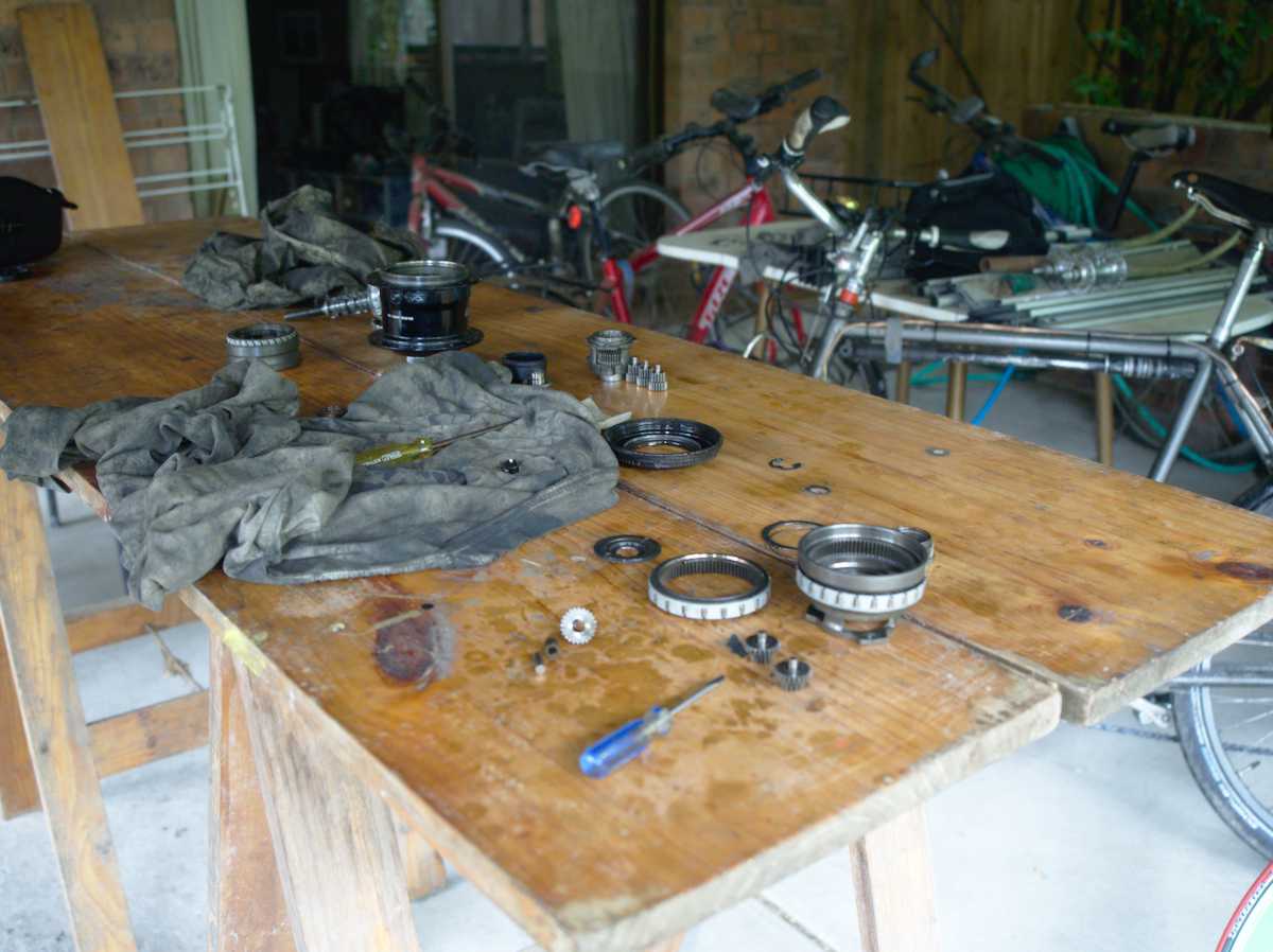
For impatient readers, here are the photographs I took of the disassembly process. Read on for more information.
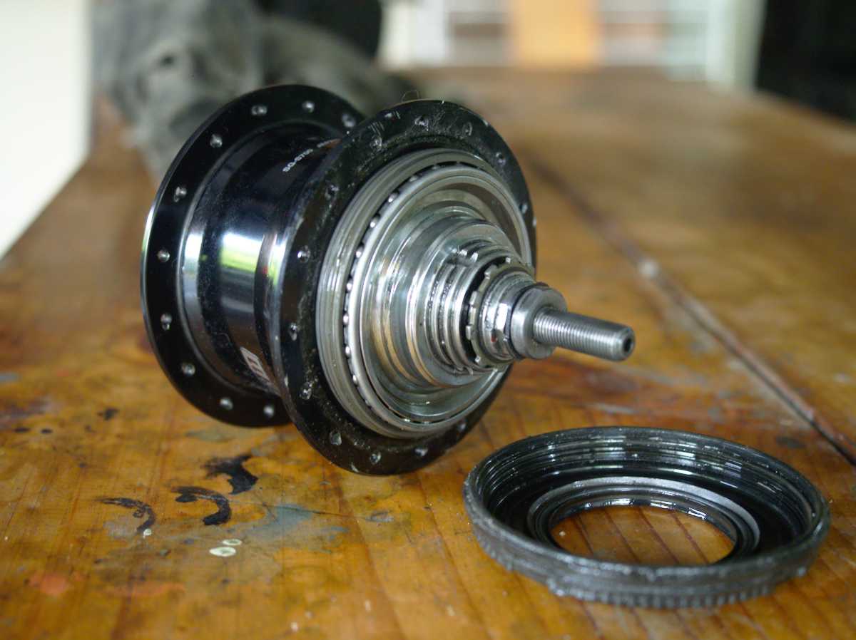
The plastic hub cap is removed. Unlike other Shimano hub gears, the hub cap isn’t attached to the internals.
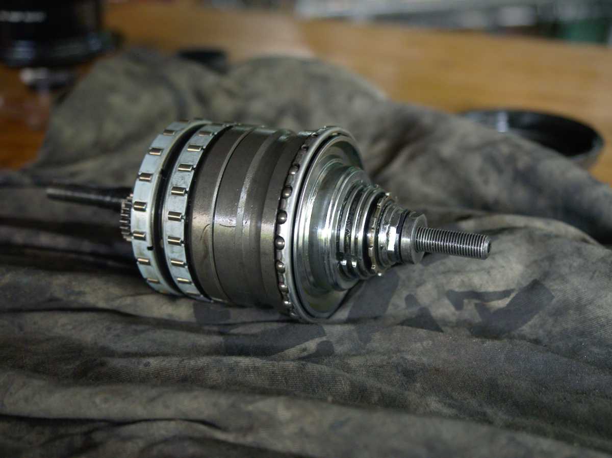
The internals. Note that the hub bearings in the big ring around the outside can’t be removed at this stage.
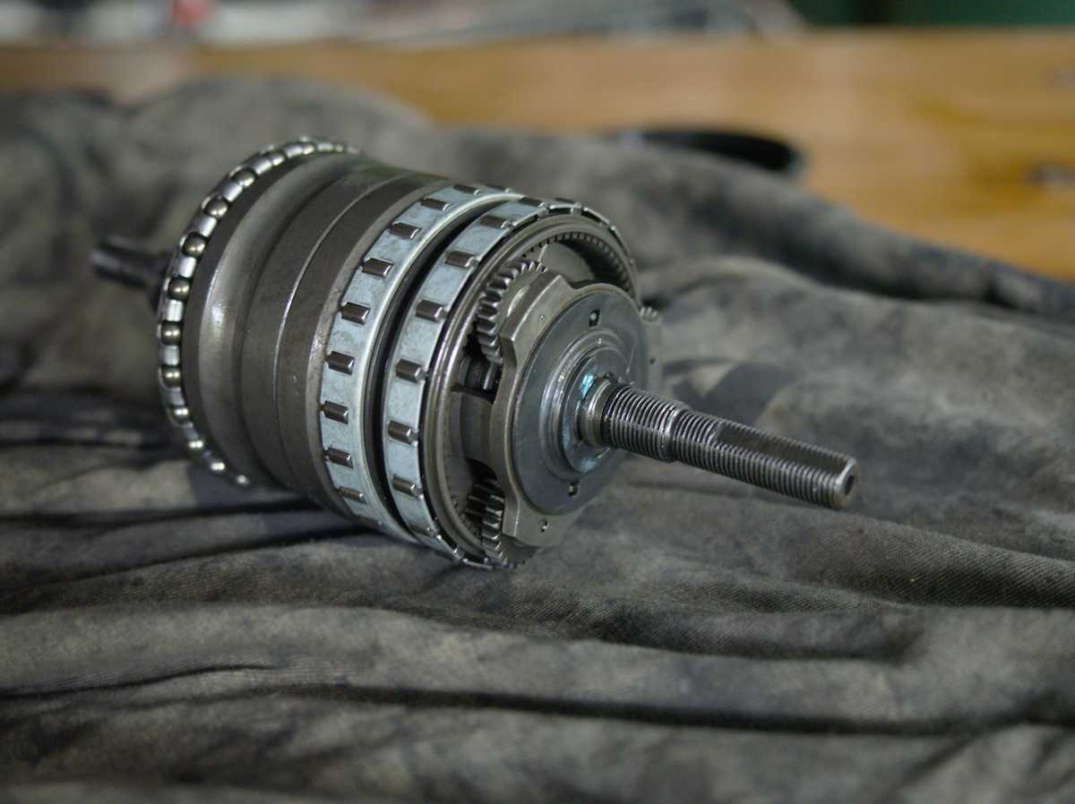
The internals from the non-drive side
This is the Jesus clip that holds the whole thing together
Jesus!!!
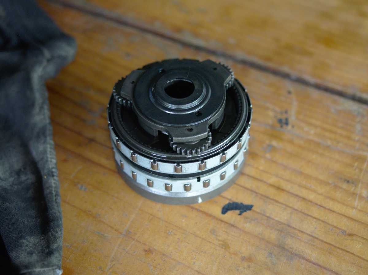
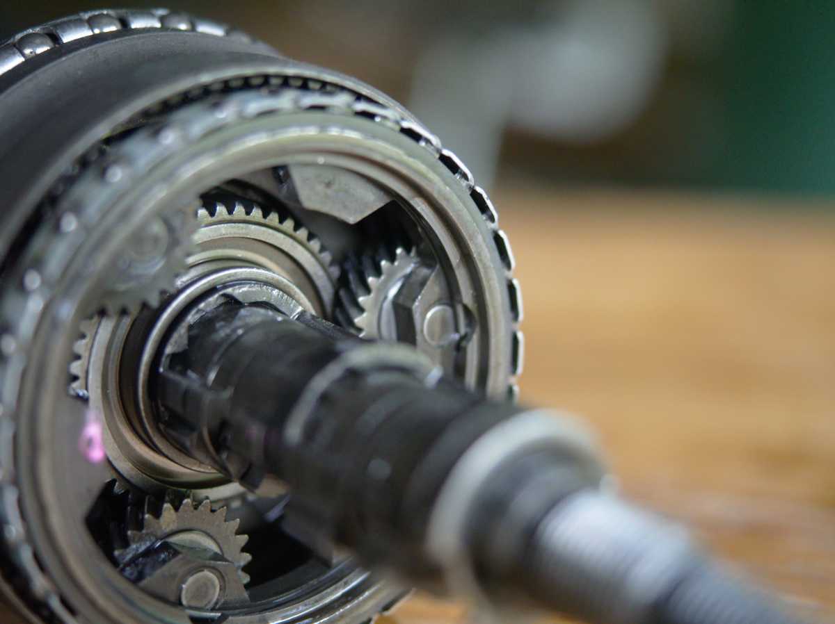
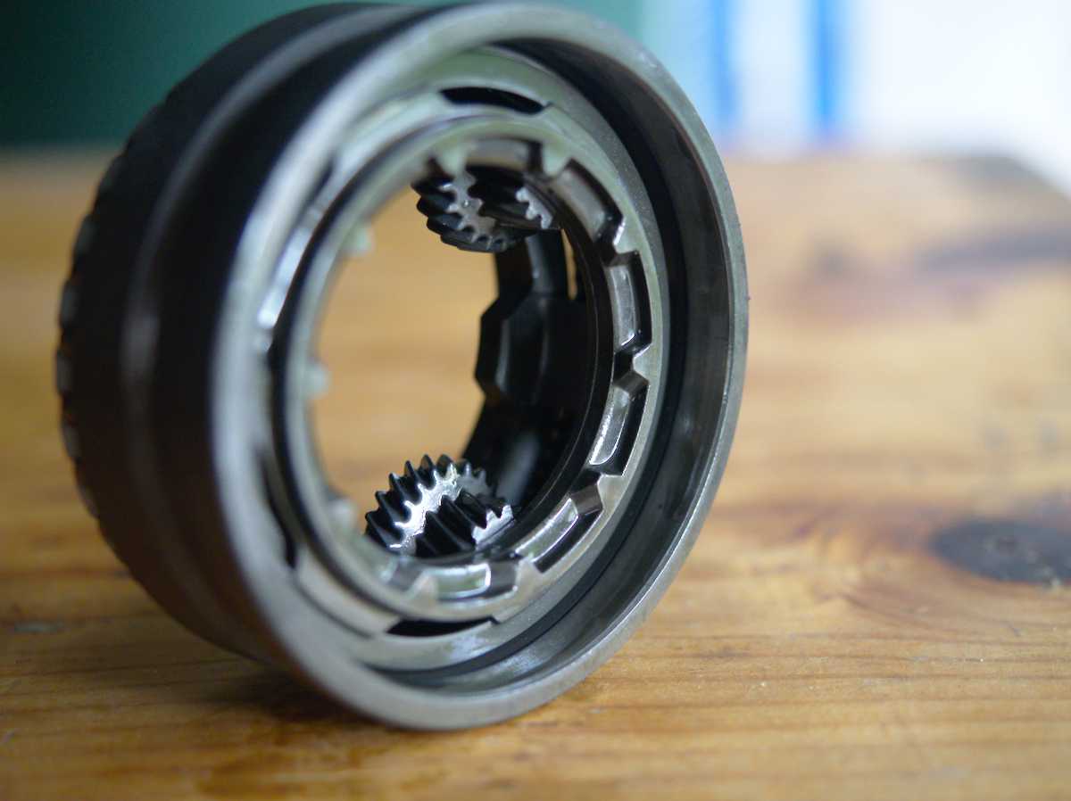
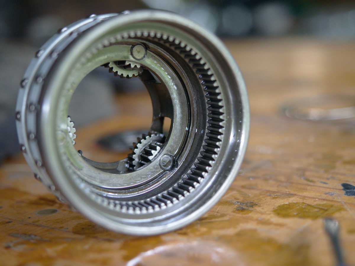
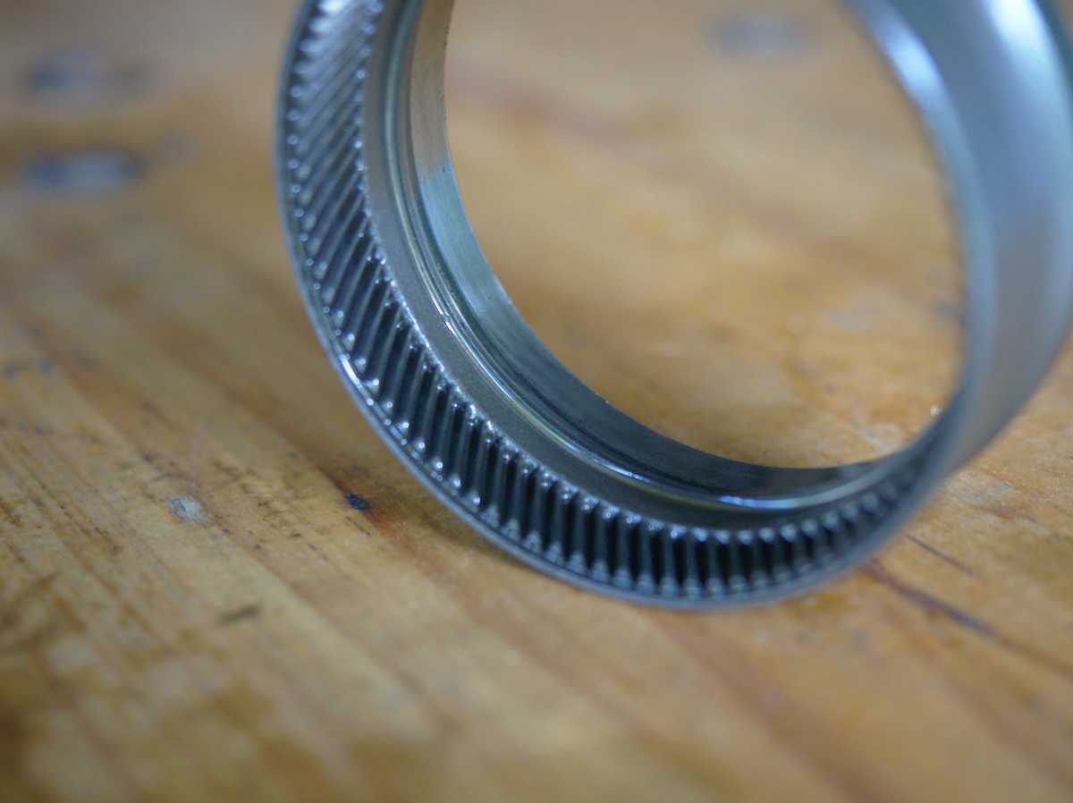
The first clump of gears to come off. Those aren’t bearings, but a roller clutch. It allows the hub shell to overrun the internals, basically like a freewheel. The gear you select determines which of these roller clutches drives the hub.
The first clump to come off, different view. The sun pinion is captive, held by another Jesus clip, so you don’t need to worry about re-syncing the planet gears unless you want to (I did). The hollow interior of the sun pinion matches a pawl on the axle.

Note the marked tooth. This is an index tooth; the index teeth on all three planet pinions must mesh with the sun pinion at the same time. If you think these marks are hard to see wait till you see the planet pinions in the other stages in this hub
This is whats left after you remove the first clump. These planet pinions only have a painted tooth for timing, rather than a stamped mark. You might be able to see how one of the teeth of the closest planet pinion is painted orange (get out those spectacles).
A closer view. At this point, you need to lower the raised pawl in the foreground to remove a small ring inside the next sun pinion.
The next basket of gears to come off. Once again there is a sun pinion that’s held captive and cannot be removed until the planet pinions have been removed.
Notice the snap-ring which prevents the planet pinion shafts from escaping.

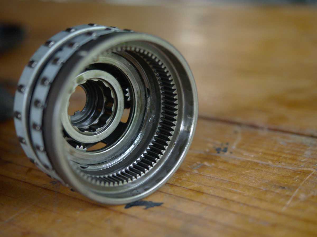
The remaining assembly. The roller clutch transmits power from the first stage to the second stage gear ring in some gears.
Notice the large dogs here. The planet carrier of the second stage slots into these.
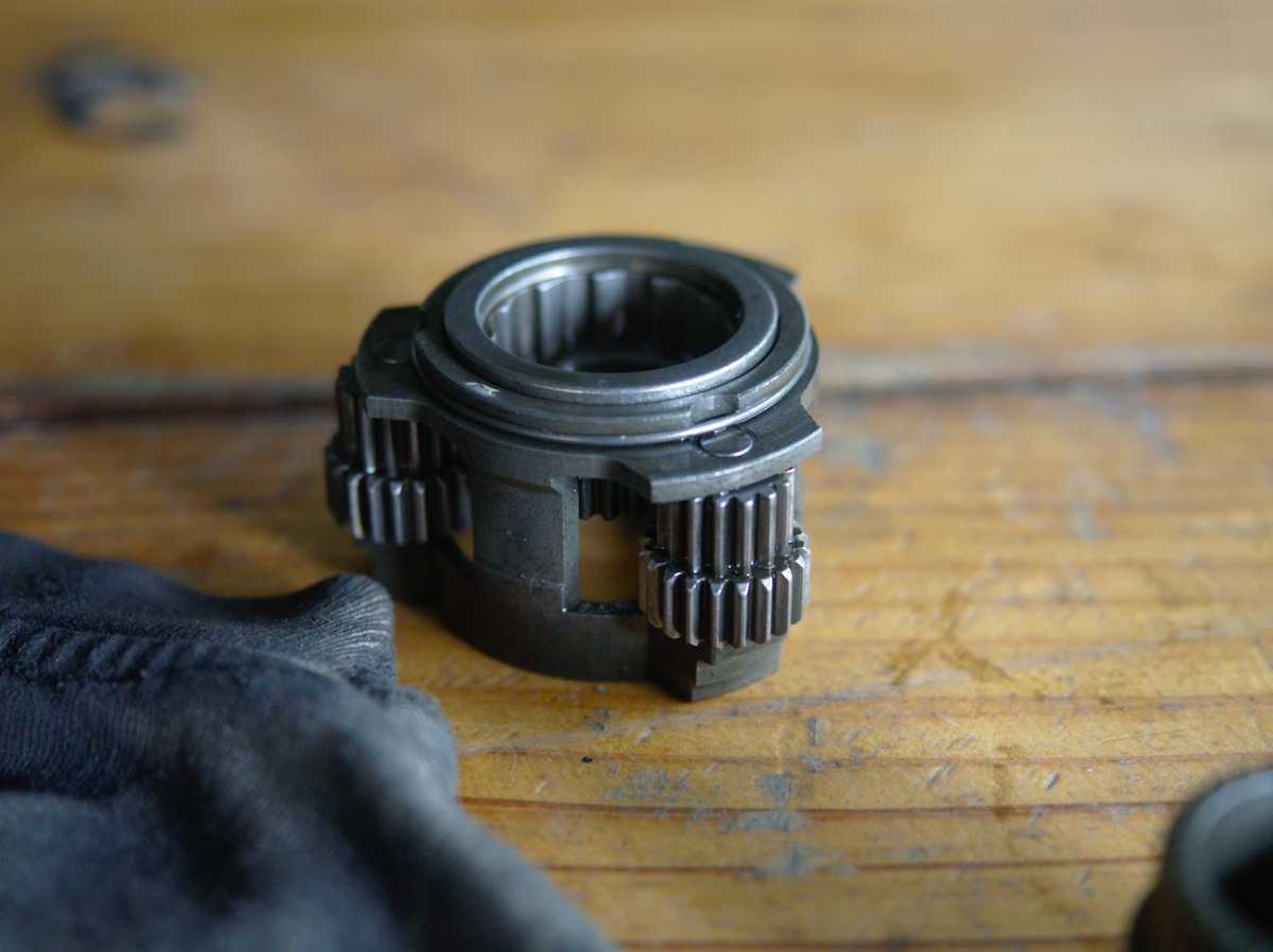
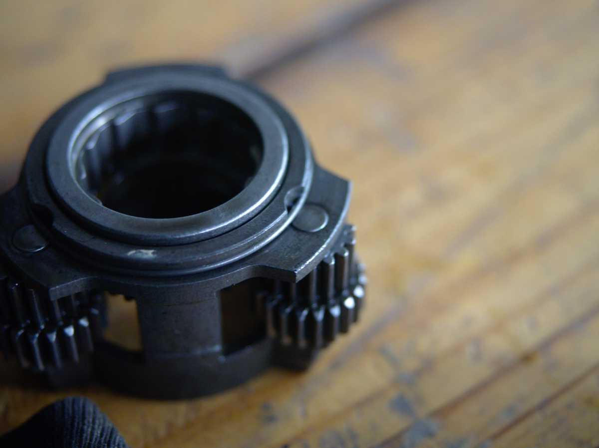
This is a clutch face on the first stage planet carrier. When the clutch is engaged, the first stage is in direct drive; when disengaged, the first stage gear ring is driven by a roller clutch providing a reduction gear.
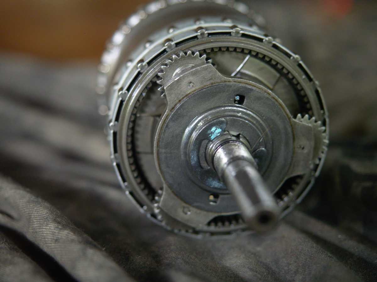
The first stage sun gear (permanently fixed to the axle), the clutch, and another roller clutch around the outside of the driver. At this point it’s possible to remove the hub bearing ring for inspection and replacement if necessary.
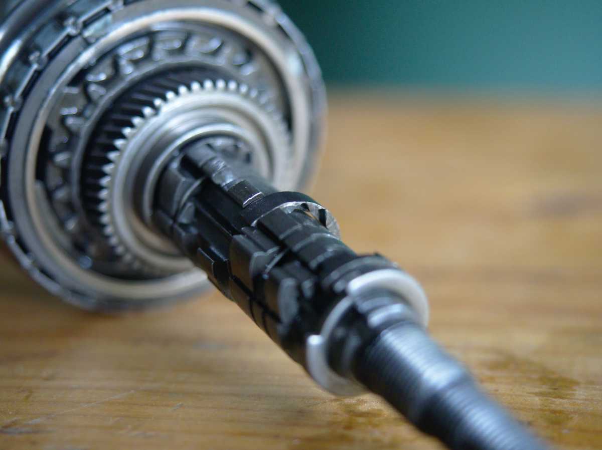
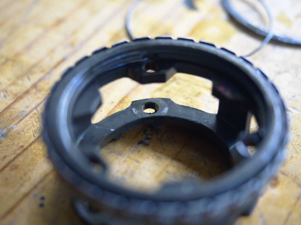
Detail of the pawl control mech. The notches allow the pawl to rise and force it down in the correct sequence. The band is rotated around the axle when you operate the shifting control.
Detail of a pawl. The wide part engages with the inside of a sun pinion. Note the tab that the shifting mech uses to lower the pawl.
For further disassembly, a magnet comes in particularly handy. These pinion shafts go into blind holes, so it’s difficult to conceive a better solution than a magnet.
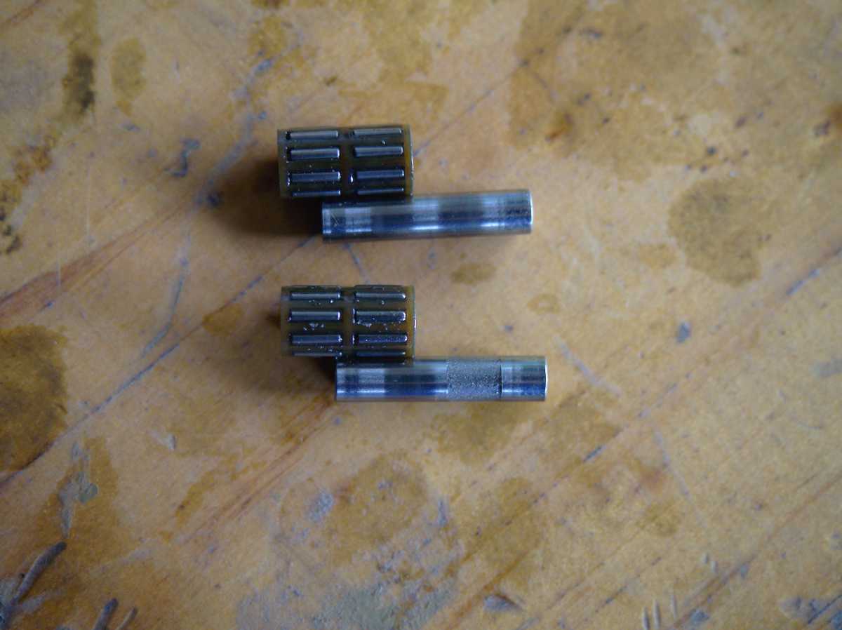
One of these isn’t looking terribly healthy (can you guess which?) In itself this wouldn’t cause any malfunction, but the shrapnel from it gets into the oil and works it’s way through the whole mechanism, and could create a more difficult repair job if this is ignored.

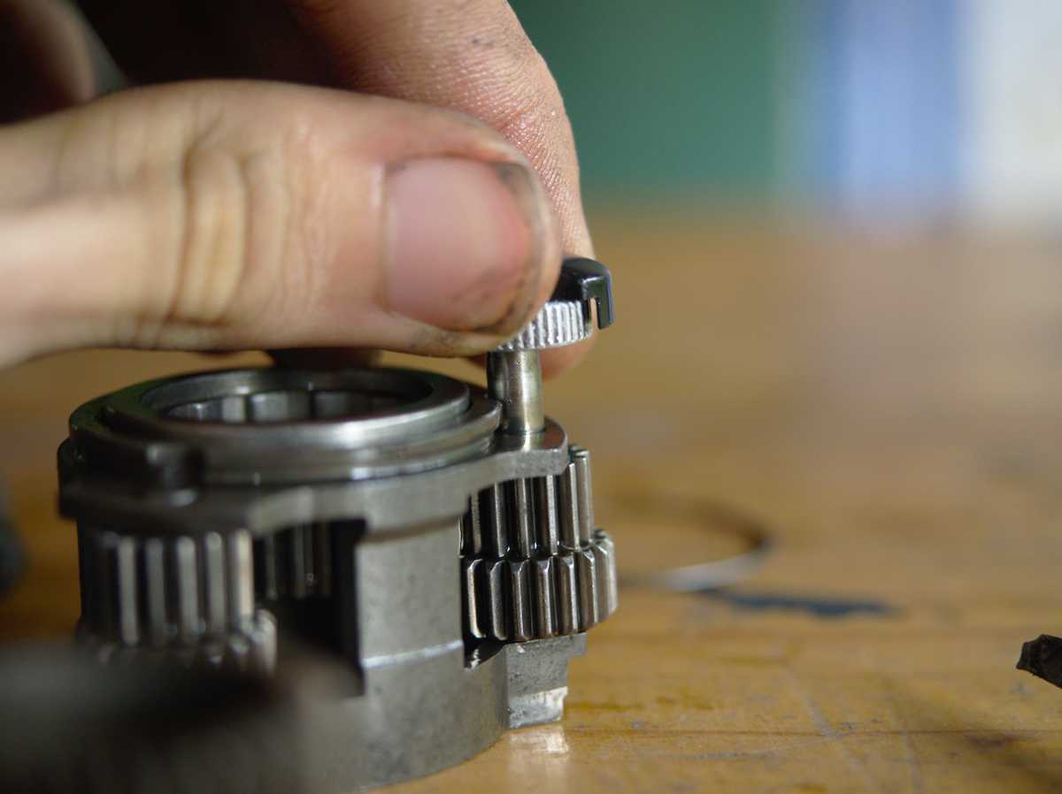
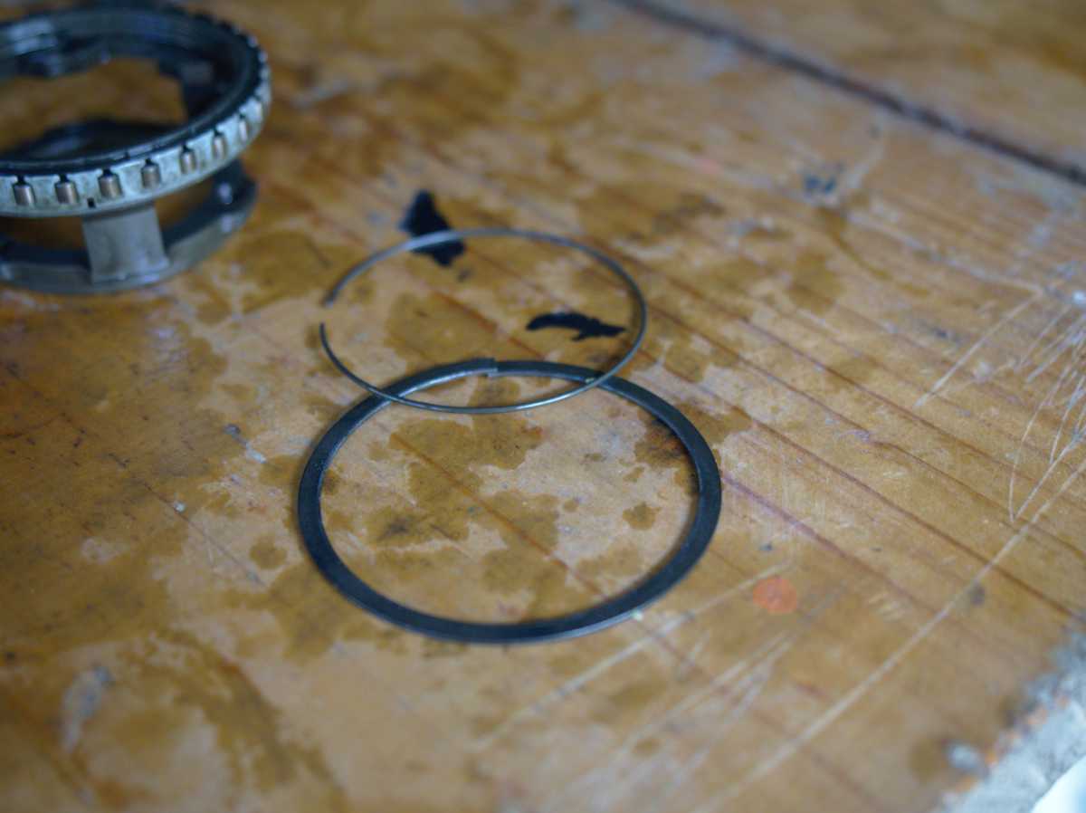
The final stage sun has a spring clip to keep it captive and avoid the fiddly process of aligning the index marks on the planet pinions. If you’re not careful it can fly a surprisingly long distance when you pry it off
Spring clip and washer that retain the planet pinion shafts. Once you’ve removed these, don’t turn the planet cage upside down, because bits fall out and go all over the place.
These exposed planet pinion pins can now be drawn out with a magnet.
All looking good.
Helical teeth on the first stage gear ring.
These snap rings need to be removed to free the planet cage on the first stage.
First stage planet cage, minus planet pinions. There is some scouring, but only lightly. There is a washer to help bear the thrust reaction load of the helical gears.
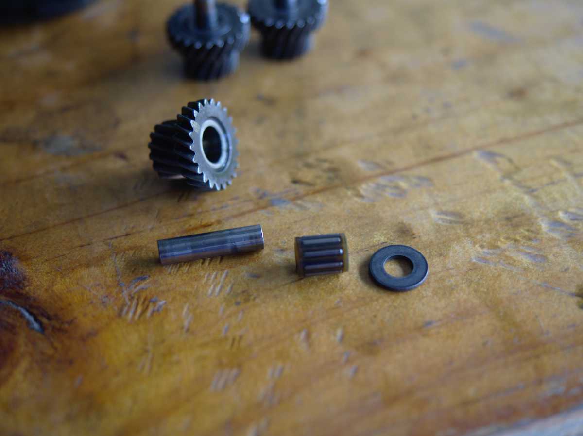
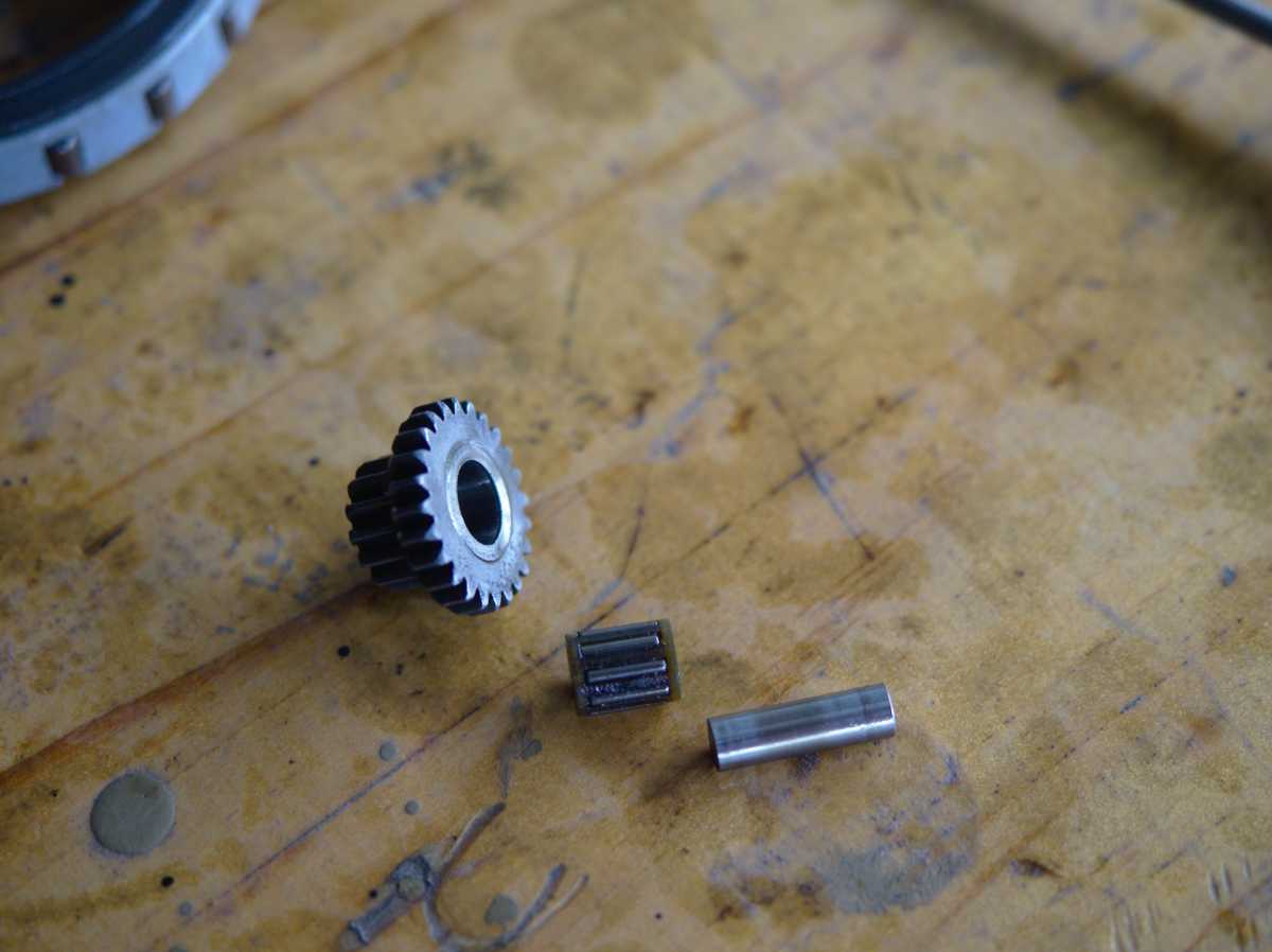
Detail of a helical planet pinion, plus shaft, needle bearings and the washer that seems to be designed to cope with the thrust load. Aligning the index marks was particularly fiddly for these ones and took me several goes. The other straight cut planets I got right first shot, since they were easier to place not because they’re straight cut.
disassembly process
As with any hub gear, the first step is to remove the wheel from the bike detaching the shift control mechanism, and you also remove the sprocket. In this case however, the hub wasn’t built into a wheel when Glenn gave it to me (after all, it’s not in service any more) and didn’t have a sprocket attached, so this “preparation” step wasn’t necessary. You should also drain any residual oil that’s inside the hub (or pull the thing apart in a tray that can contain the mess).

On the sprocket side there is a large plastic hub cap. Shimano make a special tool to undo it which is worth getting or fabricating yourself. You may be able to undo it by hand, but don’t rely on that. I couldn’t, but then maybe that’s down to the puny grip strength that comes with being an IT professional. I resorted to a hammer and punch, but that’s unwise for a hub you want to use: you could easily deform the plastic hub cap which will have the hub drooling oil all over the place from then on. Importantly, take note that the dustcap is a left hand thread.
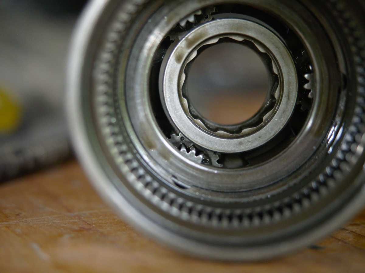
With the dustcap off you can now see the large main hub bearing race which is a frequent source of trouble in Shimano hubs through contamination with water and muck. It’s a strikingly poor design to use such a flimsy plastic dustcap to seal an oil bath hub. They could surely have used an aluminium hub cap (Rohloff style) bolted to the hub shell and sealed with a gasket, with a much smaller diameter, more robust bearing around the driver. This would all but eliminate the oil leak issue.
Anyway, you then undo the bearings on the non-sprocket end of the axle, after which the internal mechanism slides out of the hub shell. The ball bearings on the non-sprocket side are difficult to remove since they’re in a cage, and the dustcap prevents it from being removed. You can pull out the dustcap if need be, but you’ll probably damage it in the process. Leave the bearings as they are unless there’s damage to the cone.


At this stage, the internal mech is held together by the massive Jesus clip you can see on the non-sprocket end.

The gaps allow you to get a moderate sized screwdriver in to pry it off fairly easily. You may want to shield it with a rag to try to stop it from shooting across the room. Removal was pretty easy, but getting it back on again was a different story. When you’re pressing it back on with a large screwdriver, the screwdriver will slip off the narrow edge of the circlip and your hand comes slamming down on the mechanism, which is perfectly positioned to take off your thumbnail.
Having recovered the Jesus clip from the other side of the workshop, you can resume the disassembly. Like the Rohloff, it comes apart quite nicely in modules.


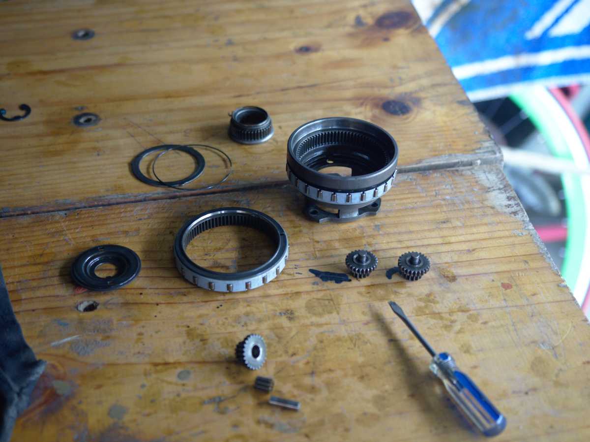
As you will know from reading Sheldon Brown’s page, this hub is a multi stage gear, being 2 x 3 x 2 to make 12 possible ratios, 11 of which are used. The first module that was removed consists of the final 2 speed stage, and the ring gear of the second three speed stage.
Next you remove a small spacer that sits inside the basket of planet gears still on the axle. It’s a bit fiddly: you have to simultaneously press down the pawl that is raised blocking the spacer from coming off and also try to jiggle the spacer out. Once you get it, it slides over the pawl and then you have to rotate it around the axle so that the tooth in the spacer aligns with a slot in the axle.

Then you are able to remove the next module, being the planet cage for the second, 3 speed stage. The raised pawls make it fiddly because they tend to catch on the sun pinion. I found that it was easier if I wrapped my hand around the planet pinions (so they couldn’t turn) and then turned the whole planet cage clockwise around the axle. It seems as if the sun pinion overruns the pawls, and tends to push them down.

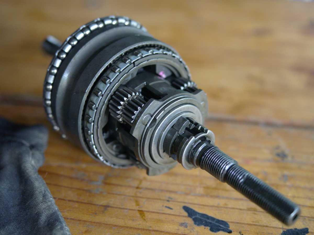
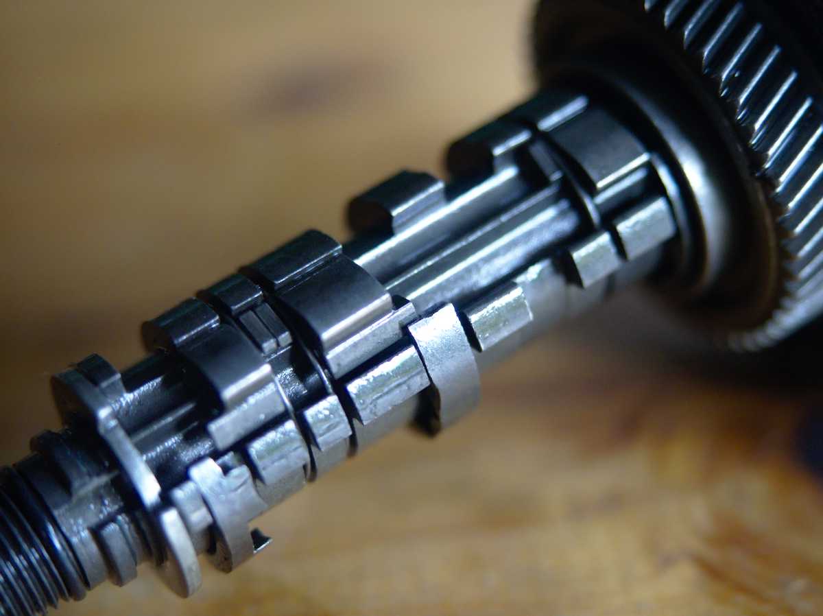
At this point, all that remains on the axle is the first stage modules. When assembled the first stage planet carrier is locked to the second stage planet carrier. They are separate modules when disassembled, but they slot together, with the form of the base of the second stage planet carrier slotting into the large dogs you can see in the first stage module.


At this point it’s possible to remove the hub bearing ring for inspection and replacement if necessary.
The final part that I removed was the module containing the planet carrier and gear ring for the first stage. The planet carrier has a snap ring around it that keeps it captive. On the sprocket side of this module, you can see the clutch face on the planet carrier which matches the clutch sitting on the sprocket side of the helical sun gear on the axle. When this clutch is engaged, power goes from the driver to the planet carrier through the clutch, and from the planet carrier to the second stage; the helical gear ring is idle, overrunning the roller clutch on the driver. If the toothed clutch is pulled out however, the roller clutch catches, and power goes through it to the gear ring of the first stage, giving a range reduction gear.
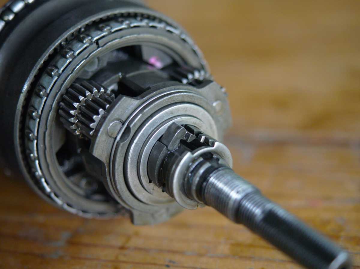
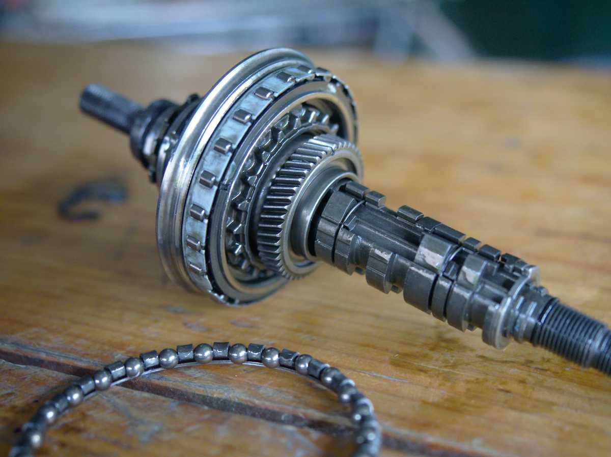
It seems difficult to carry out further disassembly of the remaining components on the axle. I managed to get as far as removing some of the external shift mechanism, but the bearing cone in the driver has no purchase for conventional tools. Is there some exotic tool required for this? How does it work? Can such a thing be easily fabricated should it be difficult to acquire through commercial means? Evidently there is some more research needed here.


Now that we’ve got to a (more or less) bare axle, it’s worth taking a look at how the control mechanism works. Rotary shift hubs seemed rather mysterious to me having mainly dealt with Sturmey Archer hubs and their pull-chains (except for the Rohloff of course). However, the rotary shifting in the Alfine is straightforward once you can look at the detail of the mechanism.
It consists of one controlled clutch (as opposed to the roller clutches which cannot be disengaged, only overrun) which we have seen in the first stage, and pawls underneath each sun pinion. The pawls are raised by a spring, and lowered by the control mech. The mechanism for lowering a pawl consists of a metal band around the axle with small detents machined on the inside of it. The pattern of the detents controls when the pawl is raised or lowered as the shift cable causes the metal band to be rotated around the axle.
This is about the level of disassembly when most people would say “done” and put it back together again, perhaps after a bath in solvent (organic solvent too, lol). All of the modules that have been removed have parts held captive so that there is no need to re-align the timing marks on the compound planet pinions. The modules go back together like leggo. But then this hub has been donated to science, so I could throw caution out the window.


First I did the module containing the second stage planet carrier. All of the planet pinions in this hub run on needle rollers, and I figured they would be interesting to get a look at. To remove the planet pinions I first removed a snap ring that secures the planet pinion shafts. I then used a magnet to coax the shafts out of their sockets. I’m not sure if a magnet counts as a “special” or “exotic” tool: I don’t consider it does since they’re pretty easy to come by.
As it happened, inspecting the needle rollers turned out to be more interesting than I’d first expected. Before I began, I’d noticed that there was some “glitter” in the residual oil in the hub shell. This is well known, and happens with Rohloff hubs too; the used oil has tiny metal particles suspended in it, little more than powder, which have been eroded from gear teeth or other surfaces. However, in this case the glitter particles were larger, more like tiny flakes of metal rather than the almost microscopic powder that I’d seen before.

In itself this wouldn’t cause any malfunction, but the shrapnel from it gets into the oil and works it’s way through the whole mechanism, and could create a more difficult repair job if this is ignored.
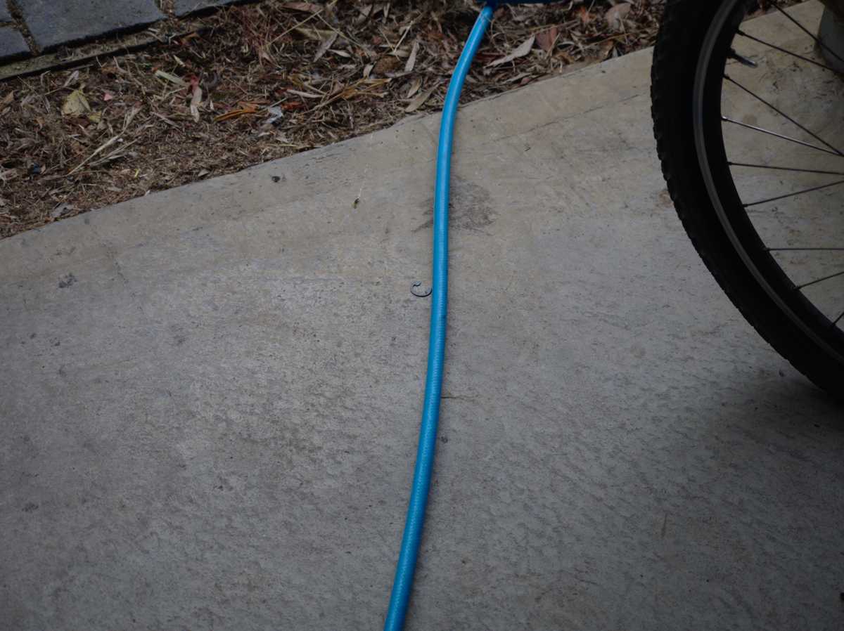
At first I thought this was simply down to differences between the Rohloff and Alfine hubs, and thought nothing of it. But then when I pulled one of the planet pinion shafts out, I found this (see photograph). There were more flakes of metal around the needle rollers of one planet pinion, and the shaft shows significant wear. From what I could see, the bearing surface inside the planet pinion was still good though, so with a small expense on steel rod and needle rollers this hub could be reconditioned and could be expected to continue to function for some time. Based on the reasoning that these parts are probably standard sizes, I’m going to try and source them from a large bearing shop not far from where I live. Once I get around to that project, that is.
When reassembling the modules, the compound planet pinions need to be correctly aligned. To accomplish this, the planet pinions all have some sort of a mark on one of the teeth (some of the timing marks are just paint and may be very hard to see; others are a stamped dot and much easier to work with), and these index teeth must all come in to mesh with the sun gear at the same time. The easiest way to align them for this particular module is to insert the sun pinions one by one, with the index tooth pointing outwards. When I did it I found it helpful to have both sun pinions inside the planet cage.
Once I’d replaced all the planet pinions (and replaced the snap ring around the top) I slotted the planet cage module into the corresponding gear ring which came off in the first module. When the planets are correctly aligned you should be able to rotate the gears with almost no resistance. If they feel tight take the planet pinions out and align them again.
I should stress that if the planets are out of alignment they will get chewed to bits very quickly should you go and use the hub in such a state. John Harland has often told the story of how his brother ruined his (John’s, that is) prized Sturmey-Archer 5 speed hub in just this way, many years ago. John is now particularly pedantic about getting the timing correct on compound planet gears, and rightly so. If you have any doubts, go back and sync them again; it could spare you from an unpleasant (and probably damaging) experience if you did get it wrong.


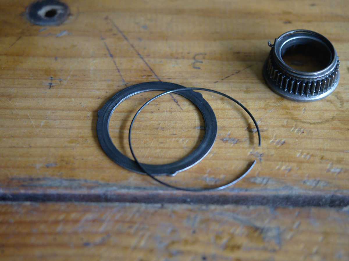
The next module I took apart was the first module to come off. You have to remove the trapped sun pinion first, by removing the Jesus clip that stops it from falling out. When I pried it off, it shot across the room like a bat out of hell (followed closely by some choice words). It’s best to put your hand over it when you pry it off (it’s very light so it won’t hurt you) that way you catch it. Next you remove the planet pinion pins, by first removing the spring clip and washer that sit inside the gear ring. The washer was difficult to prise up, so I used the magnet to lift it. The magnet is also used to extract the planet pinion pins of course.
There was no sign of damage to any of these planet pinion pins. Reassembling them was also made easier by the larger index marks on these pinions. However, while you place the planet pinions in place you have to support the gear ring for the third stage, which is rather awkward. Replacing the Jesus clip on the sun pinion that was removed is also very very fiddly.
The final module that I disassembled was the stage 1 unit, which consists of the helical gear ring and planet pinions (the sun gear for this set is fastened to the axle). There are two circlips to be removed: one secures the planet pinion shafts, and the other prevents the planet cage assembly from being separated from the ring gear. Both of these I pried off with a flat bladed screwdriver without difficulty.


Aligning the index marks was particularly fiddly for these ones and took me several goes. The other straight cut planets I got right first shot, since they were easier to place not because they’re straight cut.
Once more the planet pinion shafts still looked in reasonable condition. It was interesting to see some scraping of the planet cage though. The scraping is also on the side that doesn’t bear the thrust reaction of the planet pinion when the first stage reduction gear is in use. This thrust reaction is due to the fact that the gear teeth aren’t straight but on an angle, which behaves like a ramp. When the reduction gear is engaged, the planet pinion pushes against a washer separating it from the planet cage. However, when the first stage is in direct drive mode, the gear ring spins freely, but subject to some drag from the roller clutch it overruns, and possibly also from the oil bath. With the planet cage driving the gear ring, the reaction thrust would then be reversed, which could explain the wear marks.
Putting this module back together was also the most fiddly. The planet pinion shafts have to be inserted from the opposite side to the timing marks, which meant the technique I’d used of placing the planet pinion with the index tooth facing out would be difficult. Instead, I would have to drop the gear ring over the planet pinions with none of them getting nudged out of alignment in the process.
In practice, the “nudging out of alignment” bit is the problem, which I’ve experienced before when John pulled his Rohloff hub apart. The planet pinions will move with the slightest touch. I found that I needed them to have more resistance so that the gear ring could touch the planet pinions without throwing them out of alignment. A piece of old bicycle inner tube stretched around the outside of the planet carrier did the trick, although I then had to fish it out from a small gap with a screwdriver.
With all of the modules back together, reassembly is quite straightforward, with all the modules going back on as they came off. For the second stage planet carrier and sun pinions, it helped to turn the whole module backwards over the pawls so the pawls don’t get in the way of the sun pinions sliding along the axle.
The other fiddly step in the reassembly was installing the Jesus clip, which we’ve covered already.
As we see, the Alfine 11 hub isn’t all that difficult to strip down and reassemble. Like many Sturmey-Archer hubs and the Rohloff, there are no “special” tools required that you can’t find in any shops (provided you don’t have to pull the control mech apart at least). Given the issue I saw with one of the planet pinion bearings, it may be a good idea to do such an inspection every once in a while, especially if you’re comfortable about doing it yourself.
Great write up. Your photos are exceptional as well (nice use of focus…)… You’ve presented this disassembly clearly and concisely. I am very impressed.
My friend’s Alfine hub “slips” on occasion regardless of the gear… I’m guessing it’s shot, but your write up gave me a much better understanding of how the doggone thing works. My rough understanding too, is that the newer Shimano Alfine hubs have a different oil bath configuration allowing for oil to be added, much like the R0hloff?
Anyway, great job… thanks for the thorough presentation.
Thanks man
You’re correct that the Alfine hubs use an oil bath, although their seals aren’t as well designed as the Rohloff and they tend to seep oil more.
Sheldon Brown’s page mentions that almost all malfunctions of Alfine hubs are down to cable adjustment issues. Your friend’s hub is very unlikely to be shot; s/he just needs to fiddle with the barrel adjuster.
It gets kind of interesting though, because (according to Sheldon again) sometimes the “correct adjustment” that results in no slipping is when the little dots are up to a millimeter out of alignment, due to Shimano’s manufacturing tolerances. So if it still slips when the dots are aligned, you could be in for a fiddly trial-and-error process.
Hey Matt…
…thanks so much for the meticulously implemented write up. My Alfine 11 got damaged by the tip of the protective boot over the shift cable getting pinched between the cable and the groove on the shift quadrant while shifting from 9th to 10th. (It was a super hot day, which may have had something to do with it.) An ugly little clicking came from the hub, and 9th and 10th wouldn’t work properly any more! All other gears being fine, I just cut the tip off the boot, and carried on my way, getting home with no other troubles. I’m reading all I can about this gear train to try to isolate the fault before taking everything apart, and you have been a great help, not only with this write-up, but all the other sources you mention as well. Of course, I’ve voided the warranty by using other than Shimano lubricant in the hub, so I guess I’ve just got to get smart, and get to it!
Thanks again, and keep spinning. If you have any suggestions, that would be awesome!
Hi Matt,
I think I am in deep trouble. I cannot time the gears correctly, it seems. Is there a tool for doing it?
I’ve just been letting the two main parts bed together and have assembled by the book (with the exception of not aligning the gears).
The issue now is on the up shift (into higher gears – when detensioning cable) it goes awfully awry, does not keep the mark. I’ve replaced cable and shifting mechanism anew but no dice.
Do you have some advice for me? I’m lost…
Kind regards,
Sorry about the delayed response, I’ve been on holidays over the past 2 weeks.
I’m not aware of any tool to time the gears correctly; and I’ve always done it by hand.
Some of the teeth on each planet have a mark (a small indent or a spot of paint) and these teeth (on all three planets) must engage the sun gear at the same time.
If it isn’t correctly timed it shouldn’t affect gear changes; but rather the gears would rapidly chew themselves out (like if you force a screw that is cross-threaded or has the wrong thread pitch).
So I suspect that this may just be a cable adjustment issue, and hence easier to solve.
Out of curiosity, to what extent did you pull your hub apart?
Did you completely separate the sun, planets and ring gear? Or did you keep the sub-assemblies together?
Good article. if I remove the return spring for the gear selector cable will that then enable the mechanical hub to work with the motor unit and electronic shift buttons? Is the spring the only difference between the mechanical shift and electronic shift hubs?
I’m afraid I don’t know the answer to that one.
It would seem logical to me that Shimano would design their electric shift hubs without a return spring in the hub, since a stepper motor would be able to move the shift control both ways (a single cable can only pull one way).
I understand that removing the return spring is a very fiddly process. Aaron Goss has written up how to take apart the hub shifting mech for an 8 speed hub: http://www.rideyourbike.com/shimano8axleunitassemblyinstructions.shtml. The 11 speed shift mechanism seems to be similar, but I haven’t pulled apart that bit just yet.
Even the electric shift type contains the return spring in the hub. This can be
seen in the diagram of the hub which can be obtained from Shimano.
It looks some people believe the wrong information about the return spring of the electrical type. The origin of the wrong information is:
https://lizards.opensuse.org/2012/10/17/ot-shimano-alfine-11-di2-seis-and-backwards-compatibility-with-existing-hubs/
Difference between the mechanical type and electrical type are right side of the hub.
So we can not put the electrical shifter on the mechanical type without chainging some parts.
How weird that they included a return spring when a stepper motor could easily provide the return torque.
Do you have a link to the diagram you mentioned?
My Alfine 11 had been totally silent for over four years when it started making slight cracking noises when spinning the crank, especially when going uphill; It was still silent when coasting.
After opening the right hand-side part, I noticed the ball bearing cage was broken:
https://postimg.cc/grvHbfKm
In the article, you write that “the large main hub bearing race which is a frequent source of trouble in Shimano hubs through contamination with water and muck”, followed by “The ball bearings on the non-sprocket side are difficult to remove since they’re in a cage, and the dustcap prevents it from being removed. You can pull out the dustcap if need be, but you’ll probably damage it in the process. Leave the bearings as they are unless there’s damage to the cone.”.
I have a couple of questions:
1. Since I’ll buy new parts anyway, should I go ahead and replace the three ball bearings (part 13 “Ball Retainer S (3/16″ x 26)”, part 18 “Ball Retainer P (3/16″ x 13)”, and part 36 “Ball Retainer (7/32″ x 9)”)? https://postimg.cc/Bt5yXGbh
2. How should the tools (“TL-S701 Cone Removal Tool”, “TL-S702 Cone Removal Tool”, and “TL-S704 Mounting Tool”) be used to replace the right hand-side ball bearing?
Thank you.
Regarding replacement parts: It sounds like part 36 (RHS bearings) and possibly part 34 (RHS cone) might have to be replaced. If you replace with loose bearings instead of caged you could avoid having to pry out (and risk damaging) the rubber dust cover on the RHS bearing cup.
As for the Shimano cone removing tools for the LHS cone, I do not know how they are used. The left side cone (sprocket side) is not screwed onto the axle, instead it is pressed into place.
The cone removal and mounting tools are only for the sprocket side cone; the RHS cone is threaded like normal.
Hi Matt,
Thanks for a great and very detailed write up!
I am experiencing an issue with low mileage Alfine 11 hub which after installation seem to have only 1, 2 and 7 gears working. All the rest gears are stuck if I try to move the pedals (with my hand only, no ridding obviously) it feels very stif and pedal range in max 10 degrees. It feels like there’s a handbrake applied or the slight movement you get when you put your car in park at a slight incline and release brake pedal.
Shifter does shift ok to every single gear and aligns on yellow marks. You can also see pedals slightly move once shifting through the gears indicating that there’s movement inside the hub.
I did change the oil and cleaned the internals before putting everything to place only to discover this issue (internals looked great, no signs off excessive wear). Wheel however moves freely if I spin it by hand forward or when walking the bike.
Just by fishing for any information I was advised the following:
I am planning to take it apart and and check all the accessible modules for timing but questioning myself if it would be obvious on how to put it back together (specifically timing for each module) and test it before everything is back in the shell. Can you test the gear planet movement by hand or is it under tension?
Sorry for a long post and thanks in advance for any further suggestion or solution!
Regards,
Assuming it hasn’t been taken apart before, I highly doubt that the problem would be caused by incorrect timing of the planet gears. The timing would have been set correctly in the factory, and the only way the gears could come out of sync is if the planet gears are separated from the sun and ring gear such that the planet gears can turn independently of each other. Even during basic disassembly, if you keep the modules together, the planet gears will remain correctly synchronised.
It may be a fault with one of the roller clutches as you mentioned. I’m afraid I haven’t encountered that type of failure before so there isn’t much that I can tell. There are a total of 4 roller clutches in the Alfine 11 though, and you won’t need to re-synchronise the planet gears in order to inspect the roller clutches (because you won’t need to disassemble the basic modules).
As I recall, you can test the movement of the individual planet gear assemblies when the hub is disassembled, by turning the ring gears of each module by hand. They should turn quite freely.
Thanks for your response.
As you said, I doubt it was taken apart. I did go ahead and took it apart based on your instructions by major module, no intervention beyond that. All planet gears seem to be intact as do roller clutches, one part that seems to have wear is clutch unit (next to sprocket).
Gears on Module 1 and 2 spin freely but just for a certain travel, then it stops and can be spun backwards the same travel. I guess this is normal?
Module 3 gears spin freely continuously.
Here is a link with my photos taken:
https://ibb.co/album/SRfgxQ
Photos A4 and A5 show few worn teeth on clutch unit.
However, as this clutch engages with module 3 I doubt few worn teeth could drive my issue as other teeth from the clutch unit should compensate for it. This is just my guess though. Would you beg to differ?
As it requires special tools I am not rushing to tackle it without having any confidence that it could be the true culprit.
Pawl seems to be ok too, at least to my eye.
Thanks again,
To anyone who comes across similar issue to what I’d described above – make sure your internal planetary gears are not contaminated by swarf from other gears or, in my case, sliding clutch unit. Below is the link with a few photos of metal shaving evidence that I collected from the valleys of the gears:
https://ibb.co/album/SRfgxQ