This is based on an article that I wrote for Spokenotes, my bike club’s newsletter, but reworded and with more pictures. Pictures and diagrams are actually a very powerful learning tool for engineering; as an example, I learned how a 14 speed gear hub works primarily from a book that is written in German. I can’t read or speak German at all, but I could understand the pictures and diagrams in the book, and even spotted a mistake in one of them. But I digress. Hopefully from this article you will not only learn how to pull a dynamo hub apart, but you will also get a good idea of how they actually work. Having a background in physics would probably be useful for the latter, but hey, it’s not like it’s general relativity; I learned about electrical generators in high school.
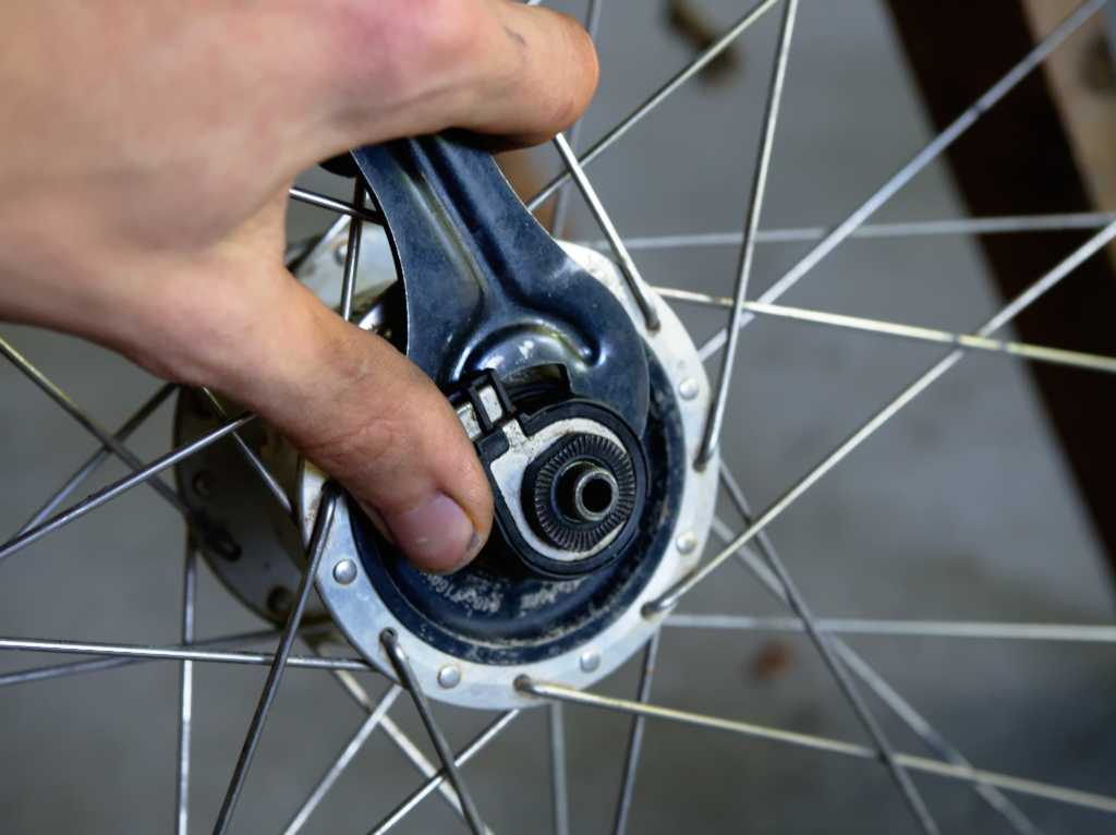
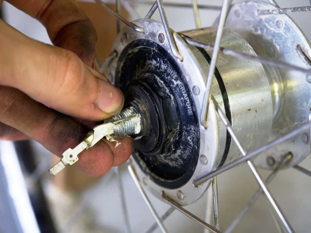
Undoing the right side locknut. Brace the terminal box with your thumb
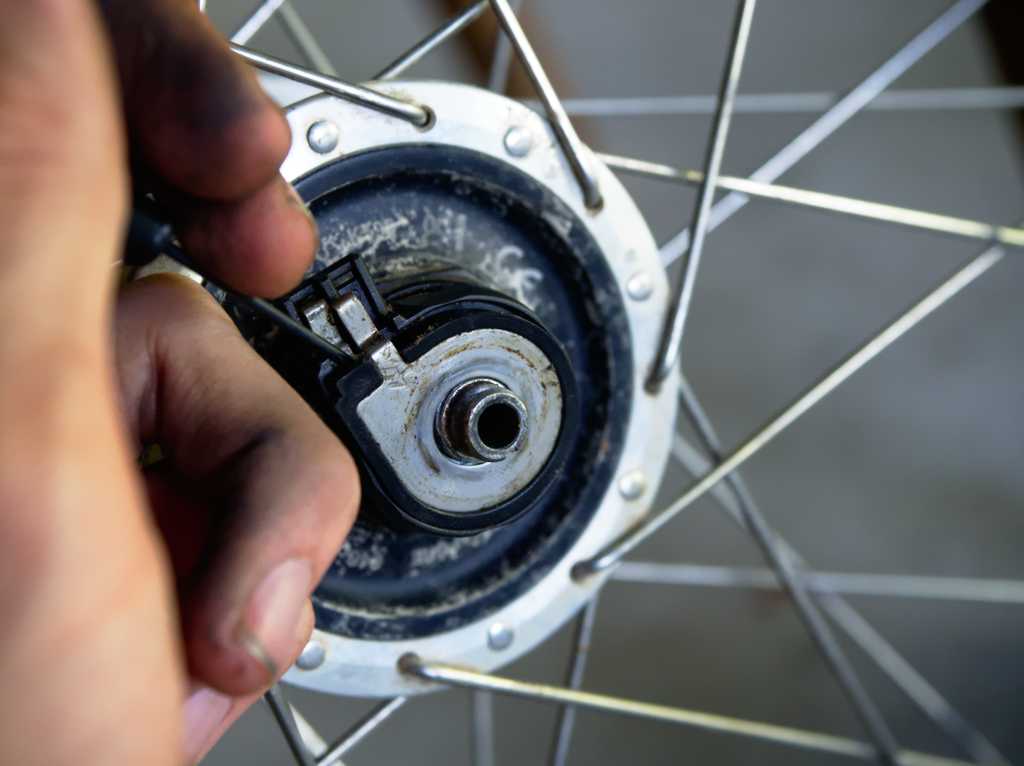
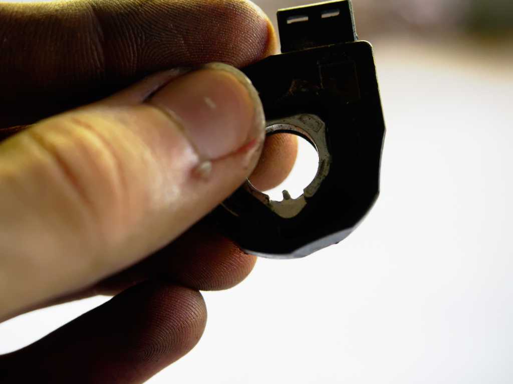
Prying off the earth plate from the terminal box
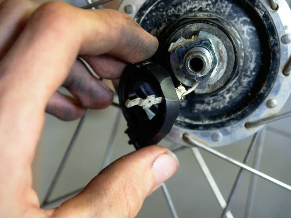
The large plastic bit has a hole in it that is just the right size and shape to fit the terminal through.
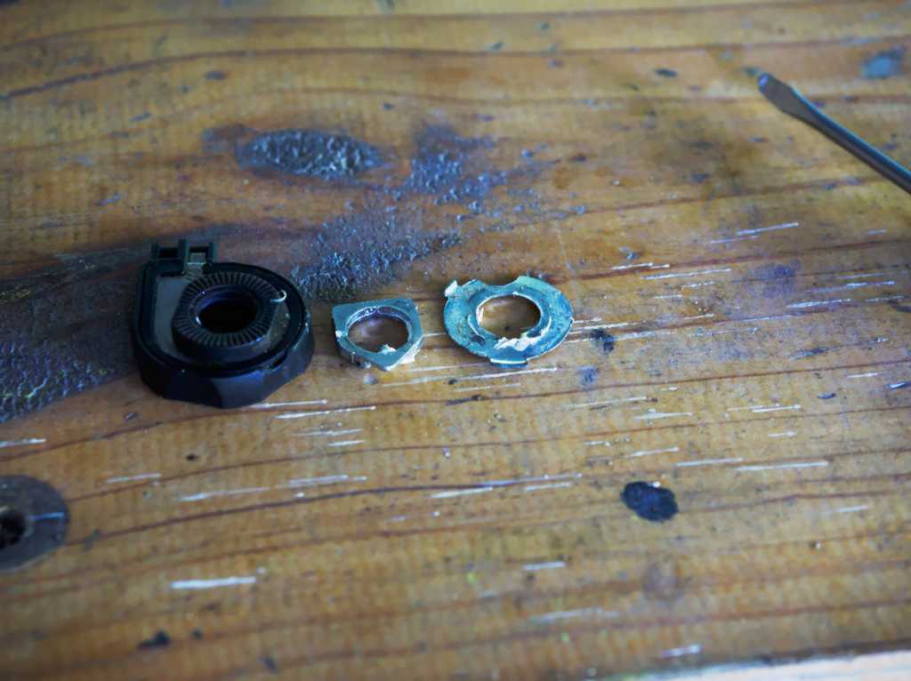
There are a few small parts, so arrange them carefully on the bench so you don’t forget how to put them back together.
Note the groove in the axle where the wire sits.
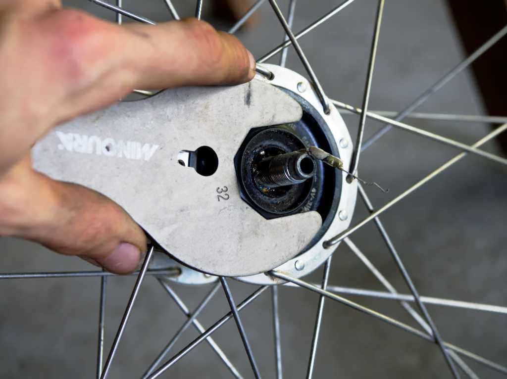
Undoing the hubcap. Although you need a large spanner, in my case it didn’t take a huge amount of effort.
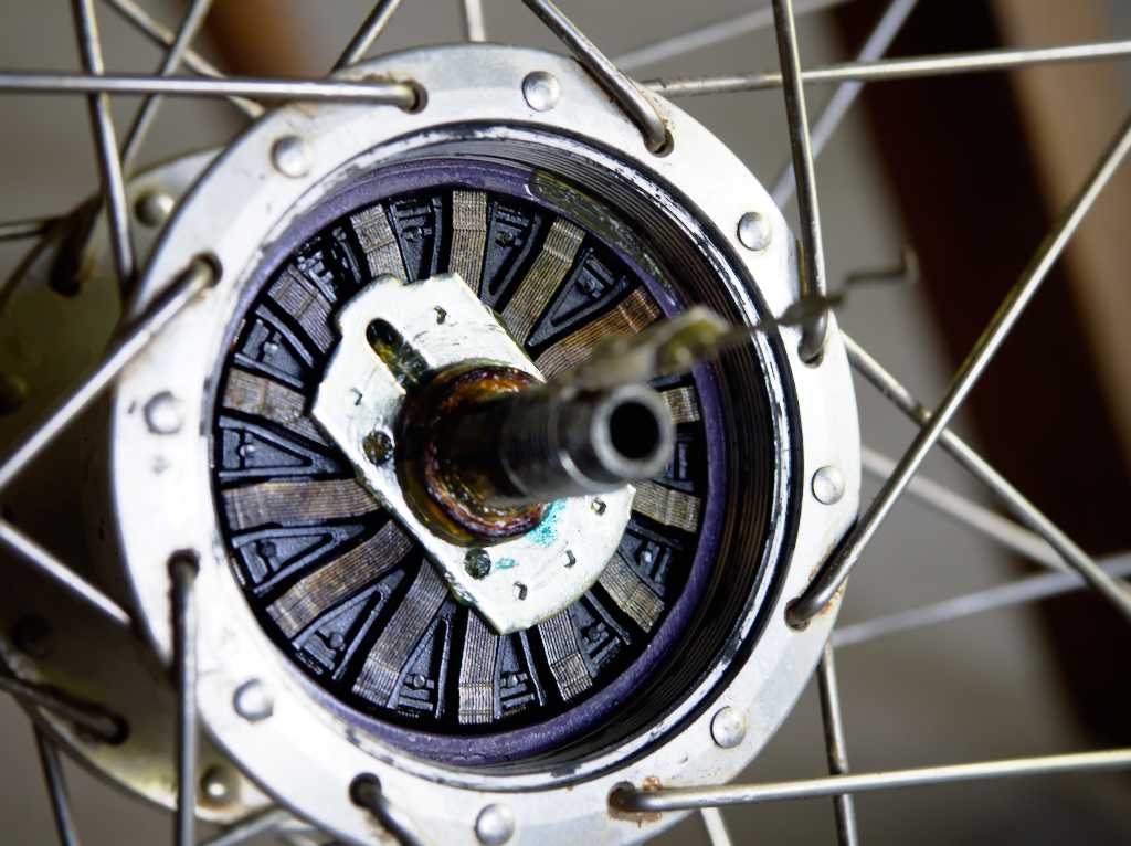
The armature inside the hub. The purple ring around the outside is the magnet; it has many poles (20 or thereabouts) with the field going inwards towards the axle.
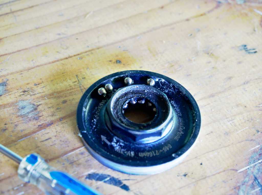
You can remove the hubcap complete with ball bearings inside.

Left hand side is the same as an ordinary hub.
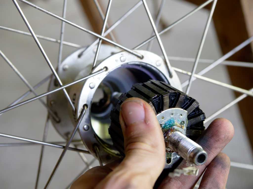
Removing the axle and armature
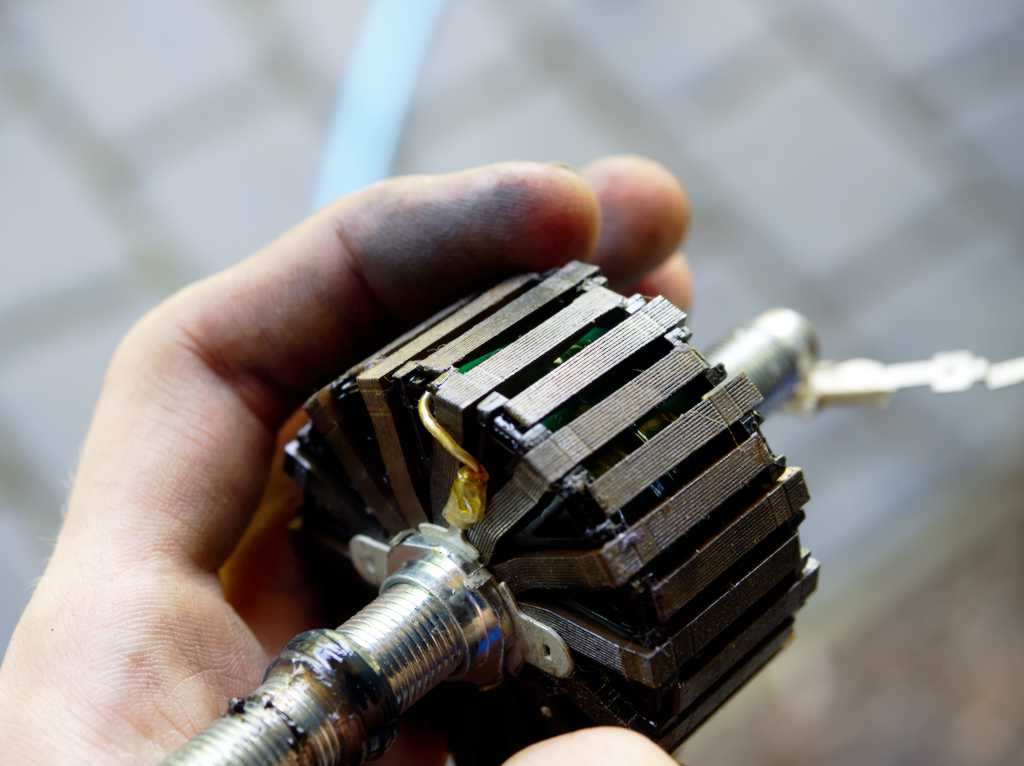
Armature assembly. Note also the wire that is connected to the axle; this is the earth side of the armature coil.
I noticed this spur on a metal washer that sits in the terminal box. It engages with the groove in the axle, and helps stop the terminal box from turning too far.
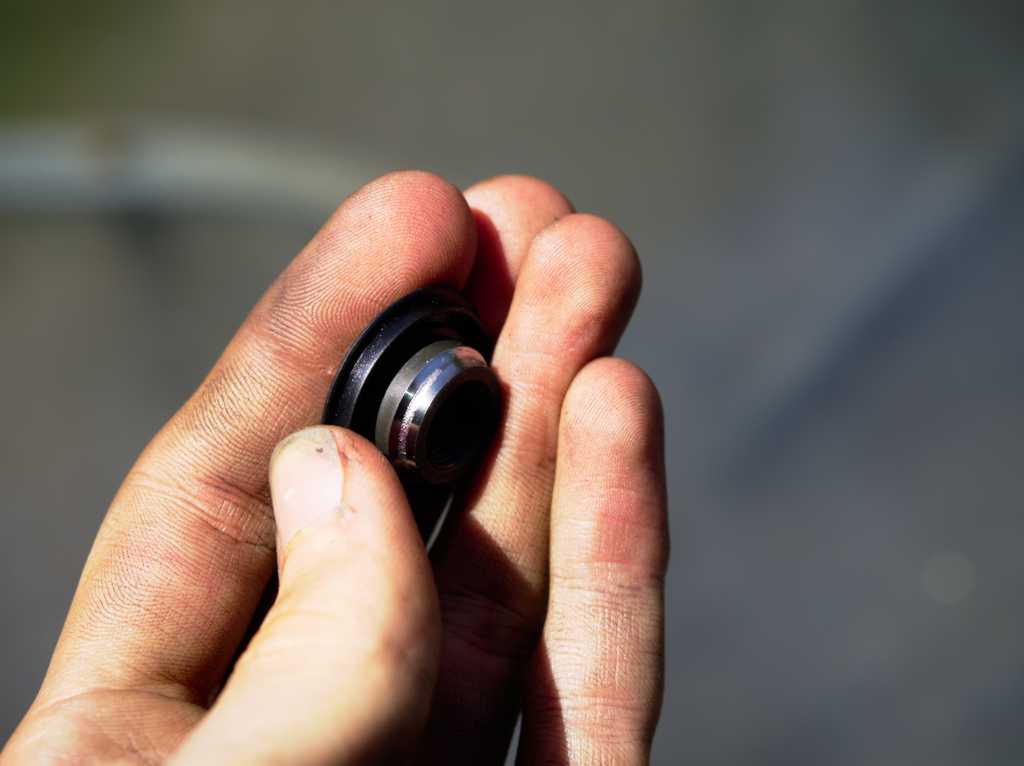
A worn cone
Another worn cone. Both of these have been replaced, fortunately in time to avoid damage to the cups. All of the ball bearings were also replaced for good measure.
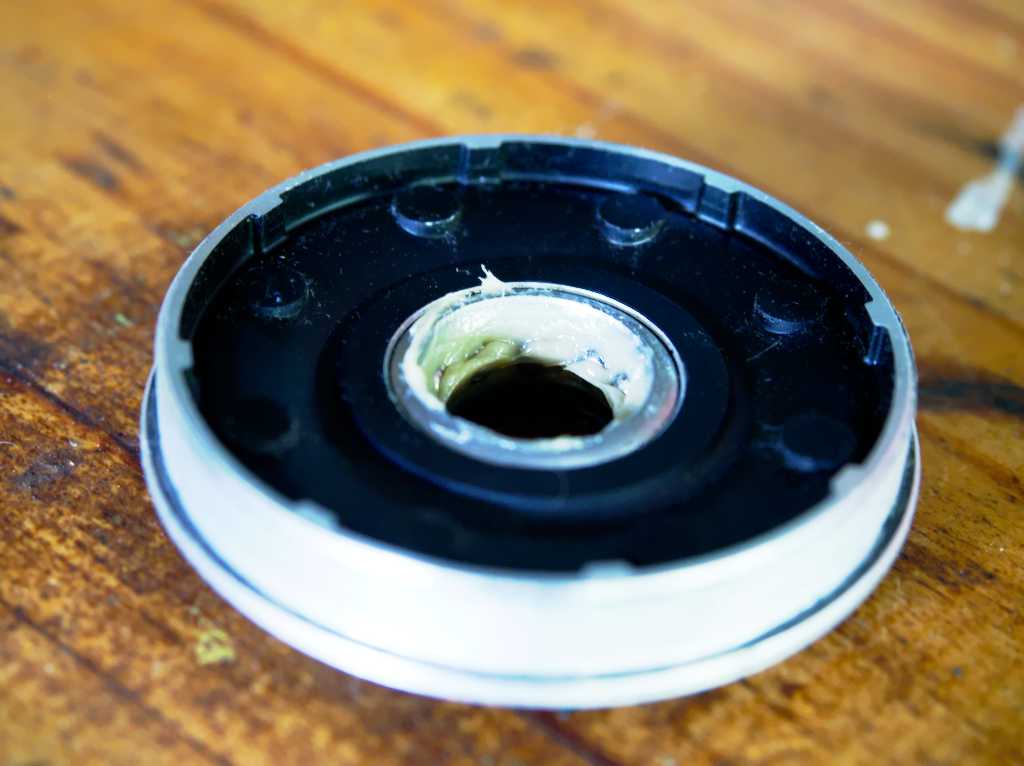
To reassemble, the right hand bearings can be packed into the hubcap on the bench, which is simpler.
A dynamo hub is a type of a hub that also generates electricity, which may be used to power lights, charge batteries etc. There are quite a few different brands around; my Dad uses a Schmidt hub, and they are very good, and correspondingly expensive. They are also more tricky to pull apart (I don’t say impossible, note), so “overhaul” for most people is synonymous with “replacement”. Having said that, the same is probably true of many owners of Shimano hubs, which can be pulled apart without any exotic tools. Most sane, rational people would probably go to a bike shop and get a “professional” to fix it, but well, where’s the fun in that?
I have had my dynamo hub since July 2011, which is about 4 and a half years at the time that I did the overhaul. I’m not sure exactly how much distance it has covered in that time, but upwards of 20,000 km would be a reasonable estimate. During which time the bearings have had no fresh grease. Ever. So the slight rumbling sensation that I could detect (feel as well as hear) as I spun the wheel was kind of worrying, and I decided it was time that I had a look inside. I also get intensely curious about anything mechanical that is sealed away from view, so the rumbly noise also provided the perfect cover story for me to satisfy my curiosity.
I should also mention that adjusting the bearings of a hub like this is tricky: The generator in the hub produces a notchy sensation as the armature rotates over the poles of the magnet, which feels a lot like bearings that are too tight. But the notchy feeling isn’t caused by the bearings. If the bearings are too tight you should expect to feel the normal notchiness of the generator and also a second more fine grained notchiness from the bearings.
Moving on to how to take your hub apart, you will remember I said that Shimano hubs can be pulled apart with ordinary tools. Well here is a list of what I needed to pull mine apart:
- 15 mm cone spanner.
- 17 mm spanner for the locknut.
- 32 mm spanner to undo the hubcap. Although a really big spanner like this might seem like an exotic tool, it is actually the same size as the nut used on many old school threaded headsets, so such spanners are available, and I had one lying around. If you have a really big shifting spanner that will probably do as well.
- A pick, or another fine tool is also useful for taking apart the terminal box. I used a really fine phillips head screwdriver (usually used for electronics).
- Cleaning equipment to clean bearings and cones. Rags come in handy too.
- Grease for repacking the bearings.
Some terminology as well: When referring to a particular “side” of the hub, the “right side” is the side with the terminal box and the “left side” is the other side, without the terminal box. The “armature” refers to the assembly on the axle, consisting of a coil of wire through which the magnetic field is directed. Some people might refer to stator and rotor; in this case the rotor (the rotating component) is a permanent magnet and the stator is the armature.

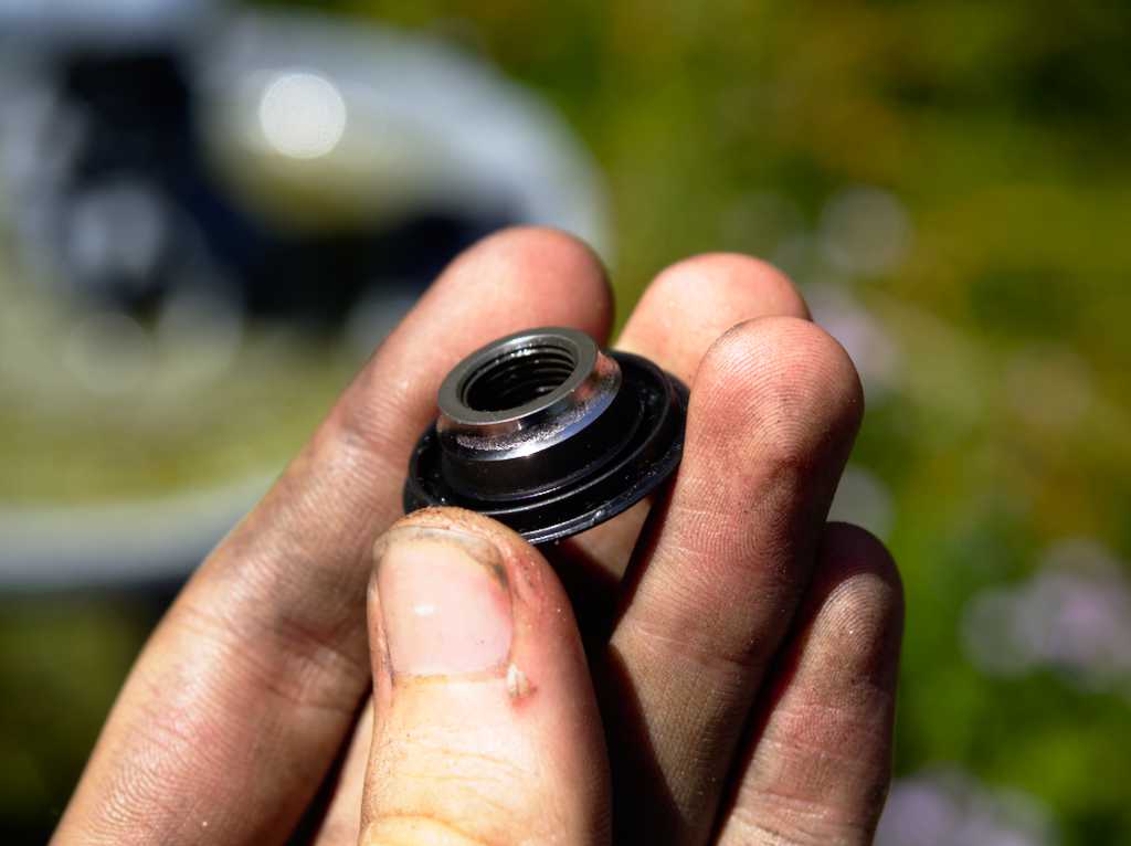
Anyway, the first step in pulling it apart is getting the wheel off the bike, and also remove the quick release skewer or else it will get in the way when you want to undo the cones. Next you need to undo the right hand side bearings, starting by taking off the terminal box. Slide the cone spanner behind the terminal box onto the flats of the cone (you might need to clean this narrow gap with a rag if you enjoy mud wallows) and unscrew the locknut. Be careful: the terminal box will try to turn with the locknut, but don’t let it move any more than a few millimeters. Hold it still with your thumb. There is a wire inside it, and if you turn it too far this wire will break, and the electrons won’t be able to get through any more. You will have to engage in other fun activities like soldering in order for the electrons to be able to get through again.

When you have taken off the locknut, pry off the earth plate with your pick, and lift off the rest of the terminal box. Take note of what order things come off in, and their orientation; which side of each part faces inwards. Also, you will notice there is a wire curled around the inside of the plastic bit. Try not to bend this wire, but rather guide the plastic bit around the curve to remove it. My reasoning for this is based on some materials science: Bending a piece of metal causes fatigue, which makes it more likely to break.

Before you unscrew the right side cone, you will notice that there is a groove cut into the axle. When you unscrew the cone, the wire will sit in this groove and hopefully not get ripped apart by the threads on the cone (you can’t avoid bending the wire here, note). If it is the first time that you have disassembled the hub though, there will probably be some white rubbery material around the cone. Make sure you clear it away, especially from inside the groove where the wire will sit.

The right hand side bearings are actually contained inside the hub cap, and you will find that the axle and dust cover makes it nigh on impossible to remove the bearings while the axle is in the way. My approach (as advised by others) was to unscrew the hubcap with ball bearings inside, from the hub, and then pick out the balls (use tweezers if you like) on the bench. Provided you’re careful, none of the ball bearings will fall out and get lost; and the sticky grease on them helps stop them from going far if they do fall out onto the floor.
So now that you have one set of bearings out and soaking in kerosene, let’s move on to the left hand bearings. Undo the locknut with the 17 mm spanner, then and this bit is really important, take note of the distance from the outside of the cone to the end of the axle. Count threads, get out your vernier calipers, whatever. That way you will know how far in the cone needs to be when you put it back together.
Once you have undone the cone, you can pull out the axle and armature from the hub, and then pluck the bearings from the left hand race, and that’s it, disassembly done.

The construction of the armature is quite interesting, and pretty much all dynamo hubs follow the same design that was originally pioneered by Sturmey-Archer with the very first “Dynohub”. As you will have learned from high school physics, electricity (specifically, voltage) is generated by a changing magnetic field passing through a coil of wire. In this case, the magnetic field is provided by a permanent magnet, which is the rotating part (eliminating the need for brushes; less moving parts translates to greater reliability). The coil of wire bit is were it gets complicated. What you see on the armature, the laminated metal bit, is what’s called a magnetic circuit; that is a magnetisable pathway from a north pole on the permanent magnet ring to a south pole (it’s made out of iron, which becomes magnetised very easily). Every second lobe goes towards the same end of the axle, and then underneath, right next to the axle itself, passing through a coil of wire which is wound around the magnetic circuit. As the wheel rotates, the magnet moves too, and all of the lobes that were next to a north pole move to a south pole, reversing the direction of the magnetic field through the whole magnetic circuit. The changing magnetic field through the coil of wire induces a voltage, and voila, useful electrical power.
If, like me, you have taken apart an old hub then it will be worth while to inspect the cones and bearings for wear. In my case the cones needed to be replaced. Because I didn’t have spares just lying around and I kind of wanted to use the bike over the next few weeks, I put the hub back together again, and put “new cones” on the shopping list. Shimano does not seem to have anticipated people like me, and they don’t sell right hand cones as a separate part (the entire “internal assembly” is one part number), but fortunately their hubs were not designed by morons; both of the cones are identical and you can just buy two left hand cones.
When you’re done playing around with the bits, putting it all back together is basically just the reverse of pulling it apart. I put plenty of grease in with the bearings given that I don’t really want to service them very often, and I also smeared a film of grease over the outside of the armature and around the magnet ring inside the hub, just in case of any contact (which really should never happen). Tightening the bearings was tricky without being easily able to test if they turn freely. What I did was I tightened them up finger tight then backed it off a bit, and tested to see if there was any play detectable at the rim. After a couple of attempts, I was happy with it. Of course, I had to do the whole rigmarole again about a month later after my new cones arrived.
So that is the story of how to pull apart your dynamo hub. A bit of preventative maintenance which will hopefully keep it going for another 5 years or so, and which also minimises waste going to landfill or recycling.
Hey Nice work Matt,
Ed told me about the blog and it’s some great reading so thanks for sharing. I didn’t know you were into electronics but there you go. I’m a hapless hifi nut but unfortunately know next to nothing about the internal workings. Have gone from valve amps and low efficiency speakers to the other end of the scale with power hungry Magnepan speakers and Hypex NC400 class D power amps which use very little power.
Cheers,
Andy
Can you clarify the armature design? Are alternate lobes all connected to one lead? For example, if I were to color the lobes alternately black and white, would all the white lobes be connected by one lead, and the black ones connected by another? And are the coil winding(s) one long piece of coated copper wire, or are there several connected in series or parallel?
I’m trying to design and build a dynamo to go on the non-drive side of a rear wheel, attached/clamped to the hub, so I’m just trying to visualize how a bike dynamo would be modified to fit my application.
To use your example, if the armature lobes were coloured alternately black and white, each black lobe may face a north pole on the ring magnet (which is a permanent magnet), and each white lobe would face a south pole. The armature carries the magnetic field from the north pole (black lobe) through the center of the coil, and then back out to a south pole (white lobe).
The technical term for this I believe is a claw-pole design, which should help with your research.
The coil is a single coil of wire (I would expect that it would be magnet wire/enameled wire, as that would be most suitable for this application). There are many windings (I would say dozens at the least, possibly over 100). The output terminals are connected to each end of the coil.
The coil is a bit hard to see in the photos because it is inside the laminated armature; the coil is kind of wound around the axle. The green plastic you see in one photo seems to be a cover over the windings (I can’t tell what purpose the cover serves though).
Your project sounds very interesting, good luck!
Hi Matt, IMHO it will be much easier if you started the disassembly by removing the left cone, then unscrewing the assembly from the hub, as if you wanted to replace it as a whole. You can then deal with the fiddly bits on your workbench, or with the axle clamped in a vice, without the rest of the wheel getting in your way.
Greasing the iron parts of the armature is a good idea, not because of possible contact with the magnets (if that happened your bearings would either be very badly misadjusted or completely shot), but because of rust. There can be severe condensation on the inside of the hub.
Remo, Zürich
I think you’ve done a terrific job with this article. I stumbled across it after searching online for a “terminal connector box”, which was completely absent from an old dynamo hub I wanted to service. Sadly, and surprisingly, it seems that this particular part is not replaceable. (I didn’t come across anyone trying to replace just that damaged/missing part, let alone find any on the planet — even a used one — for sale.) I also didn’t come across anyone else trying to service this dynamo hub to the extent that you did. In this “throw-away” world, your efforts are to be commended!
Thank you
Out of interest, which part of the terminal connector are you trying to replace? There’s the bit that the wires to the lights go into (which plugs onto the hub terminals), and then there’s the plastic terminal housing on the hub itself. I would have thought that the first part would be sold separately; maybe not so much the second (because Shimano don’t really encourage people to attempt to service or repair the internals).
For the plastic bits, 3D printing could be a solution to sourcing parts that are otherwise not commercially available. You could also produce makeshift terminals out of thin metal too.